Clock data recovery circuit, data reception apparatus, and data transmission and reception system
A clock data recovery and circuit technology, applied in digital transmission systems, transmission systems, electrical components, etc., can solve problems such as CDR operation instability, achieve stable data receiving capabilities, and avoid locked and unlocked states.
Inactive Publication Date: 2014-06-25
SONY CORP
View PDF3 Cites 16 Cited by
- Summary
- Abstract
- Description
- Claims
- Application Information
AI Technical Summary
Problems solved by technology
These requirements make the operation of the CDR unstable
Method used
View moreImage
Smart ImageViewing Examples

Examples
no. 1 approach
[0031] [First Embodiment: Overall Configuration and Operation of CDR]
[0032] [Example of delay circuit]
no. 2 approach
[0033] [Second embodiment: automatically setting the CDR of the first delay time dT1 and the second delay time dT2]
no. 3 approach
[0034] [Third Embodiment: Overall Configuration and Operation of CDR]
Login to View More PUM
 Abstract
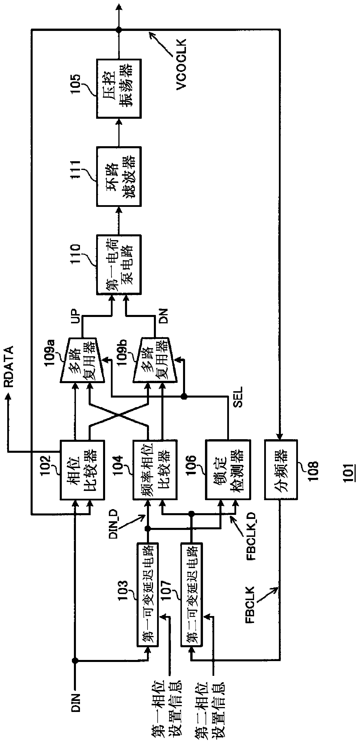
The invention provides a clock data recovery circuit, a data reception apparatus and a data transmission and reception system. The clock data recovery circuit includes: an oscillator that outputs a clock signal; a phase comparator that outputs a signal corresponding to a phase difference between an input reception data signal and the clock signal; a divider that outputs a feedback clock signal; a first variable delay circuit that outputs a delay data signal; a second variable delay circuit that outputs a delay feedback clock signal; a frequency phase comparator that outputs a signal corresponding to a frequency difference and a phase difference between the delay data signal and the delay feedback clock signal; a lock detector that outputs a determination signal indicating whether or not the frequency difference and the phase difference are within a predetermined range; and a multiplexer that receives the determination signal and select a signal of the phase comparator and a signal of the frequency phase comparator.
Description
[0001] Cross References to Related Applications [0002] This application claims the benefit of Japanese Priority Patent Application JP2012-277624 filed on December 20, 2012, the entire contents of which are hereby incorporated by reference. technical field [0003] The present disclosure relates to a clock data recovery circuit, a data receiving device, and a data transmission and receiving system. Background technique [0004] In recent years, in the fields of information equipment and digital equipment, high-speed serial communication has been widely used in order to transmit large-capacity digital data at high speed and at low cost. A receiving device of high-speed serial communication uses a "clock and data recovery" circuit (hereinafter abbreviated as "CDR") to reproduce clock and data synchronized with a predetermined encoded received data column. In order to extract the data rate (data rate) of the received data column, the transmitter sends a predetermined clock pa...
Claims
Login to View More Application Information
Patent Timeline
 Patent Type & Authority Applications(China)
IPC IPC(8): H03L7/08
CPCH04L7/0337H04L7/0037H04L7/0041H04L7/0331
Inventor 丸子健一植野洋介
Owner SONY CORP