Suction valve cover and suction assembly containing the same

A technology of suction valve and valve, which is applied in the field of anesthesia machines, can solve problems such as poor sealing, air leakage of the suction valve cover, and high product scrap rate, so as to save processing costs, avoid safety accidents, and The effect of process simplification

Active Publication Date: 2016-07-06
BEIJING AEONMED
View PDF7 Cites 0 Cited by
  • Summary
  • Abstract
  • Description
  • Claims
  • Application Information

AI Technical Summary

Problems solved by technology

The structure of the suction valve cover can make the internal valve movement visible through the glass baffle 104, and the hollow valve cover body 100 provides the necessary space for the movement of the valve valve, and the valve cover body 100 is set at the same time The connection thread 102 makes the installation and disassembly of the suction valve cover more convenient, but this suction valve cover has the following defects: 1. The structure of the suction valve cover makes the oxygen concentration sensor only be installed in the suction valve. Outside the air port, this cannot guarantee the stability of the oxygen concentration detection during the operation, which makes the anesthesia machine a potential safety hazard; The sealing of the connection method is not strong, and the threaded connection is prone to problems such as slippage after long-term use, resulting in loose connection, air leakage, and environmental pollution; 3. The structure of the suction valve cover is complicated, and the corresponding The production process is also very complicated, resulting in high production costs and a high product scrap rate; 4. By adopting a split design for the glass baffle and the valve cover body, the gap between the valve cover body and the glass baffle is also easy. Make the suction valve cover leak, waste energy and pollute the environment

Method used


Image

  • Suction valve cover and suction assembly containing the same
  • Suction valve cover and suction assembly containing the same
  • Suction valve cover and suction assembly containing the same

Examples


Embodiment 1

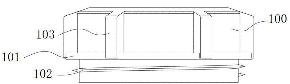
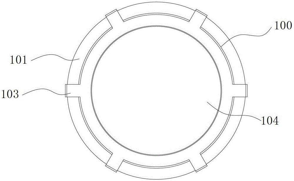
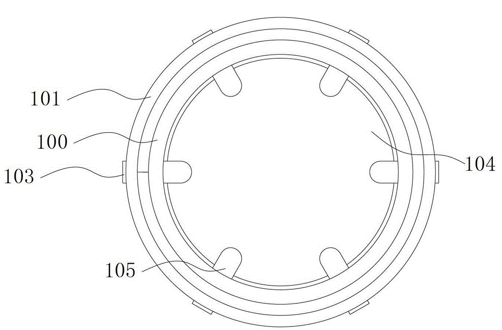
[0071] Such as Figure 5-6 As shown, the suction valve cover in this embodiment includes a valve cover body, and the valve cover body includes a circular outer wall 11, and the outer wall 11 includes a sealed outer wall first end and an open outer wall second end , the first end of the outer wall is provided with a sealing surface 13, and a connecting hole 14 is provided through the center of the sealing surface 13, so that the inside and outside of the valve cover body are connected.

[0072] The connecting hole 14 includes a first end of the connecting hole and a second end of the connecting hole. The first end of the connecting hole is arranged on the upper part of the sealing surface 13, and the second end of the connecting hole is arranged on the lower part of the sealing surface 13 (that is, inside the outer wall 11). The two ends protrude toward the second end of the outer wall with an annular inner wall 12 .

[0073] The sealing surface 13 is arc-shaped, and the seali...

Embodiment 2

[0092] The suction valve cover in this embodiment includes a valve cover body, the valve cover body includes a square outer wall, the outer wall includes a sealed first end of the outer wall and an open second end of the outer wall, and the first end of the outer wall is provided with The sealing surface is provided with a connecting hole in the center of the sealing surface, so that the inside and outside of the valve cover body are connected.

[0093] The connecting hole includes a first end of the connecting hole and a second end of the connecting hole. The first end of the connecting hole is set on the upper part of the sealing surface, and the second end of the connecting hole is set on the lower part of the sealing surface (that is, inside the outer wall), and the second end of the connecting hole faces the outer wall. The second end protrudes from a square inner wall.

[0094] The sealing surface is arc-shaped, and the sealing surface is connected with the outer wall an...


PUM


Abstract

The invention discloses an inhalation valve cover which comprises a valve cover body. The valve cover body is provided with space for containing an inhalation valve and a connecting hole used for being connected with an oxygen sensor, and the connecting hole is a through hole communicated with the inside and the outside of the valve cover body. By arranging the connecting hole on the inhalation valve cover body and communicating the oxygen sensor with the inside of the inhalation valve through the connecting hole, the oxygen sensor is enabled to be capable of timely detecting oxygen concentration inside the inhalation valve cover, so that stability in oxygen concentration detection in the process of surgery is guaranteed, and safety accidents are avoided. The invention further discloses an inhalation component. The inhalation component is mainly characterized in that the connecting hole is arranged on the inhalation valve cover, the inhalation cover is connected on a mounting seat in a pressed manner through a locking nut, and a sealing ring is arranged at a position where the inhalation valve cover is connected with the connecting seat, so that oxygen concentration detection can be enabled to be more accurate, sealing performance is high, and great convenience in demounting is realized.

Description

technical field [0001] The invention relates to the technical field of anesthesia machines, in particular to an inhalation valve cover and an inhalation assembly containing the same. Background technique [0002] An anesthesia machine is a medical machine used for general anesthesia, oxygen supply, and assisted or controlled breathing. It requires that the concentration of oxygen provided and inhaled anesthetic should be accurate, stable and easy to control. Anesthesia machines can be divided into three types according to the number of functions and the complexity of the structure: ① Almighty type: complex structure, complete functions, with electronic or computer-controlled respiratory management system, monitoring instrument, alarm system, and some automatic recording systems; ② Universal type : The structure and function are simpler than the previous item, but still have basic and important structures and components, such as safety systems such as nitrous oxide automatic ...

Claims


Application Information

Patent Timeline
Patent Type & Authority Patents(China)
IPC IPC(8): A61M16/20A61M16/01
Inventor 付超
Owner BEIJING AEONMED
Why Eureka
Try Eureka