Pneumatic control valve for anesthetic evaporator and anesthetic evaporator control method implemented by pneumatic control valve

An anesthesia vaporizer and air control valve technology, which is applied in the field of anesthesia vaporizers, can solve the problems of vaporization pressure discharge, high cost, and danger in the non-evaporating chamber, and achieve the effects of solving anesthesia leakage, saving costs, and improving safety in use

Active Publication Date: 2014-07-02
BEIJING AEONMED
View PDF6 Cites 1 Cited by
  • Summary
  • Abstract
  • Description
  • Claims
  • Application Information

AI Technical Summary

Problems solved by technology

[0003] The existing anesthesia vaporizers have at least the following defects: 1. Most anesthesia vaporizers do not have a transportation position, and the anesthetic agent in the vaporizer needs to be poured out in advance during transportation to prevent the anesthetic agent from leaking during transportation. It means that the evaporator is in a specific position, and the transportation will not cause the anesthetic agent to leak; some anesthesia evaporators have a transportation position, and the transportation position is used in conjunction with an additional independently set sliding valve and the evaporator air control valve, but the structure is relatively complicated. Defects of many parts and high cost
[0004] 2. When the anesthesia evaporator is in the zero position, that is, when the anesthesia evaporator is in a non-working state, the evaporation pressure in the evaporation chamber cannot be discharged, so that there is always a certain evaporation pressure in the evaporation chamber. When the evaporator is used urgently, it will affect Concentration of anesthetic vapors when switched on, which can be dangerous

Method used


Image

  • Pneumatic control valve for anesthetic evaporator and anesthetic evaporator control method implemented by pneumatic control valve
  • Pneumatic control valve for anesthetic evaporator and anesthetic evaporator control method implemented by pneumatic control valve
  • Pneumatic control valve for anesthetic evaporator and anesthetic evaporator control method implemented by pneumatic control valve

Examples


Embodiment 1

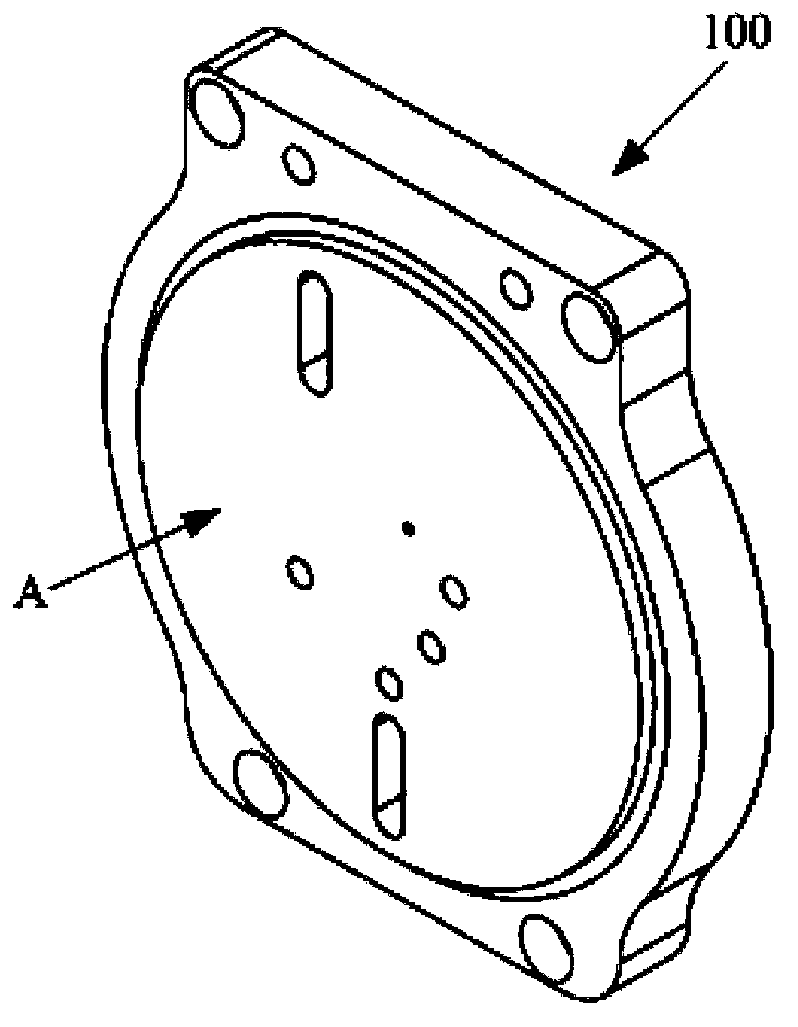
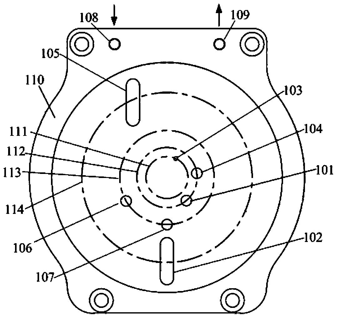
[0056] Such as Figure 2-5 As shown, an air-operated valve for an anesthesia vaporizer includes a valve seat 100 and a valve plate 200 arranged in contact with it. The valve plate 200 can rotate coaxially relative to the valve seat 100. The valve seat 100 has an air inlet 108 and an air outlet 109. And the gas channel inside the valve seat.

[0057] The valve seat 100 has a valve seat side 110 connected to the valve plate. The valve seat side 110 has four concentrically arranged annular areas with its center as the center of a circle. From the inside to the outside, there are first annular area 111 and second annular area 112. , the third annular area 113, the fourth annular area 114, the third air hole 103 connected with the evaporation chamber is opened in the first annular area 111, in order to release the evaporation pressure; the fourth air hole 104 is opened in the second annular area 112 and connected with The first air hole 101 connected to the evaporation chamber, th...

Embodiment 2

[0067] Such as Figure 9-12 As shown, an air-operated valve for an anesthesia vaporizer includes a valve seat 100 and a valve plate 200 arranged in contact with it. The valve plate 200 can rotate coaxially relative to the valve seat 100. The valve seat 100 has an air inlet 108 and an air outlet 109. And the gas channel inside the valve seat.

[0068] The valve seat 100 has a valve seat side 110 connected to the valve plate. The valve seat side 110 has three concentrically arranged annular areas with its center as the center of a circle. From the inside to the outside, there are first annular area 111 and second annular area 112. , the fourth annular area 114, in the first annular area 111, the third air hole 103 connected with the evaporation chamber is opened, in order to release the evaporation pressure; the fourth air hole 104 and the first air hole 103 connected with the evaporation chamber are opened in the second annular area 112 Gas hole 101, gas enters evaporation cha...


PUM


Abstract

The invention discloses a pneumatic control valve for an anesthetic evaporator. The pneumatic control valve comprises a valve seat and a valve plate. The valve plate is in contact with the valve seat and can rotate relative to the valve seat, the valve seat is provided with a gas inlet, a gas outlet and a gas channel, the gas channel is arranged inside the valve seat, at least a first gas hole and a second gas hole are formed in the valve seat, gas can flow into an evaporation chamber via the first gas hole, gas can be exhausted from the evaporation chamber via the second gas hole, and a first plugging portion and a second plugging portion which respectively correspond to the first gas hole and the second gas hole are arranged on the valve plate. The pneumatic control valve has the advantages that the valve plate can rotate, so that the first gas hole and the second gas hole can be plugged by the first plugging portion and the second blocking portion respectively, the anesthetic evaporator is positioned at a transportation station, all gas holes which are communicated with the evaporation chamber are plugged, and the problem of leakage of anesthetics in transportation procedures can be effectively solved; a third gas hole is further formed in the valve plate, an atmosphere communicating portion which corresponds to the third gas hole is arranged on the valve plate, and the valve plate can rotate, so that the atmosphere communicating portion can be communicated with the third gas hole, and the internal evaporation pressure of the evaporation chamber can be effectively relieved when the anesthetic evaporator is positioned at a non-working station.

Description

technical field [0001] The invention relates to the technical field of anesthesia vaporizers, in particular to an air control valve for an anesthesia vaporizer and a method for controlling the anesthesia vaporizer using the air control valve. Background technique [0002] The anesthesia vaporizer is an important part of the anesthesia machine. Its quality not only marks the level of the anesthesia machine, but also relates to the success or failure of inhalation anesthesia, directly related to the safety of the patient. Liquid volatile anesthetics, such as amflurane and isoflurane, are not allowed to enter the respiratory tract directly, nor are they allowed to enter the respiratory tract in the form of saturated vapor, because most people can achieve anesthesia at a very low partial pressure of the brain. Anesthetics have a relatively high saturated vapor pressure, for example, halothane is 32.4kPa at 20°C, but the partial pressure of the brain that produces anesthesia is o...

Claims


Application Information

Patent Timeline
Patent Type & Authority Applications(China)
IPC IPC(8): A61M16/20A61M16/18
Inventor 郑殿会
Owner BEIJING AEONMED
Why Eureka
Try Eureka