Material fluidity control method for metal plate forming

A metal sheet and control method technology, which is applied in the field of metal forming and manufacturing, can solve the problems of limited increase of forming depth, insignificant processing effect of large drawing ratio, and inability to achieve flexible control of the fluidity of sheet metal materials. Achieve the effect of increasing the ultimate drawing coefficient and suppressing wrinkling and tearing

Inactive Publication Date: 2014-07-02
HUAZHONG UNIV OF SCI & TECH
View PDF7 Cites 16 Cited by
  • Summary
  • Abstract
  • Description
  • Claims
  • Application Information

AI Technical Summary

Problems solved by technology

However, when the size of the plate to be formed is large, this method has a limited effect on increasing the forming depth, that is, the processing effect on large drawi...

Method used


Image

  • Material fluidity control method for metal plate forming
  • Material fluidity control method for metal plate forming
  • Material fluidity control method for metal plate forming

Examples


Embodiment 1

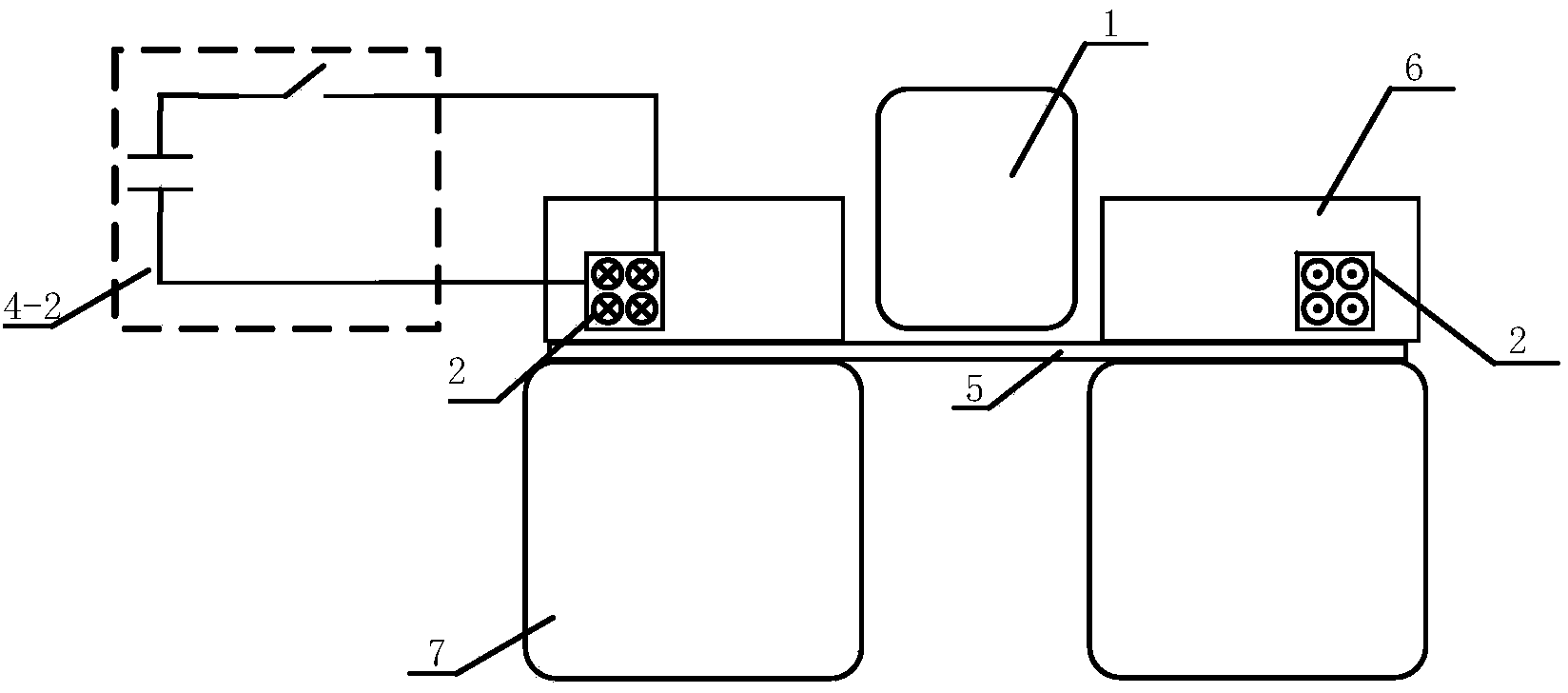
[0044] like figure 1 As shown, the sheet metal forming device includes a punch 1 , an eddy current coil 2 , a first pulse power supply 4 - 2 , a blank holder 6 and a die 7 . The metal sheet 5 is placed on the die 7, the punch 1 and the blank holder 6 are placed on the metal sheet 5, the punch 1 corresponds to the cavity of the die 7, the eddy current coil 2 is embedded in the blank holder 6, the first The pulse power supply 4-2 is connected to the eddy current coil 2.

[0045] The blank holder 6 provides blank-holding force for the metal sheet 5, the punch 1 provides the axial forming force for the metal sheet 5, and the first pulse power supply 4-2 provides timing and energy-controllable discharge for the eddy current coil 2, so that the eddy current coil 2 During the discharge process, a huge pulse current flows (the pulse width is between tens of microseconds and several milliseconds, and the current amplitude reaches tens of kiloamperes or even hundreds of kiloamperes), a...

Embodiment 2

[0057] like Figure 7 As shown, the sheet metal forming device includes a punch 1, an eddy current coil 2, an axial magnetic field coil 3, a first pulse power supply 4-2, a second pulse power supply 4-3, a blank holder 6 and a die 7. The metal plate 5 is placed on the die 7, the punch 1 and the blank holder 6 are placed on the metal plate 5, the punch 1 corresponds to the cavity of the die 7, the eddy current coil 2 is embedded in the blank holder 6, and the axial The magnetic field coil 3 is arranged on the periphery of the eddy current coil 2 and generally has more turns. The first pulse power supply 4-2 is connected to the eddy current coil 2, and the second pulse power supply 4-3 is connected to the axial magnetic field coil 3.

[0058] The blank holder ring 6 provides the blank holder force for the sheet metal 5 , and the punch 1 provides the axial forming force for the sheet metal 5 . The second pulse power supply 4-3 provides timing and energy controllable discharge fo...


PUM


Abstract

The invention discloses a material fluidity control method for metal plate forming. According to the material fluidity control method, a vortex coil is utilized to induct a vortex in a flange area of a metal plate, and an area generating an induction vortex is disposed in a magnetic field with axial magnetic field components perpendicular to the plate surface; under the joint action of the vortex and the magnetic field, a transverse electromagnetic force, which is parallel to the plate surface and points to a recessed-die cavity from the flange area of the metal plate or points to the flange area of the metal plate from the recessed-die cavity, is generated; the transverse electromagnetic force is matched with an axial forming force, so that control of material fluidity is realized. The transverse electromagnetic force adjustable in space distribution, timing sequence, amplitude and direction is generated in the flange area of the metal plate, so that flexible and multi-freedom-degree control of the material fluidity in metal plate forming is realized, wrinkling and tearing are effectively restrained, and the limit drawing coefficient is improved. The material fluidity control method is simple and can be widely used for assisting in processing of metal plates.

Description

technical field [0001] The invention belongs to the technical field of metal forming and manufacturing, and more particularly relates to a method for controlling material fluidity for metal sheet forming. Background technique [0002] Wrinkling and tearing are two common defects that occur during sheet metal processing (whether conventional stamping or high-speed forming techniques including electromagnetic forming, explosive forming, electro-hydraulic forming, etc.). When the material flow is insufficient, the material will bear excessive tensile stress, necking occurs locally, and then tearing occurs; and when the material flow is excessive, the material undergoes plastic instability and wrinkling. In order to suppress wrinkling, the main method is to increase the blank holder force and increase the blank holder rib; to suppress tearing, the main method is to improve the lubricating performance between the sheet metal flange and the die, and the blank holder ring, such as ...

Claims


Application Information

Patent Timeline
IPC IPC(8): B21D24/00
Inventor 李亮赖智鹏曹全梁周中玉
Owner HUAZHONG UNIV OF SCI & TECH
Why Eureka
Try Eureka