Mini-pile combined support structure and construction method thereof
A technology of retaining structure and construction method, which is applied in the direction of foundation structure engineering, excavation, construction, etc., can solve the problems of small flexural rigidity of mini piles and inability to expand the construction of enclosure piles, etc., and achieve high flexural rigidity and good water stop Effect, the effect of improving the bending resistance
- Summary
- Abstract
- Description
- Claims
- Application Information
AI Technical Summary
Problems solved by technology
Method used
Image
Examples
Embodiment 1
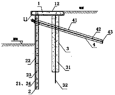
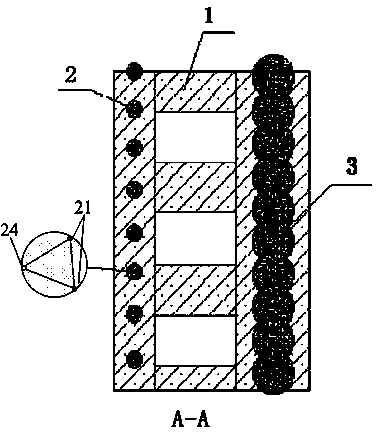
[0039]Such as figure 1 , figure 2 As shown, the mini-pile composite retaining structure of the present invention includes a crown beam 1, a mini-pile 2, a stirring pile 3 and a grouting anchor rod 4, and the crown beam 1 is composed of a crown beam stirrup 11 and a crown beam longitudinal reinforcement 12. Two mini-pile vertical reinforcing bars 21 and a mini-pile steel pipe 24 are symmetrically arranged along the pile center in the mini-pile 2, and the distance between the two mini-pile vertical reinforcing bars 21 and a mini-pile steel pipe 24 is 0.6- 0.9d, d is the diameter of the mini-pile pile; two mini-pile vertical steel bars 21 and a mini-pile steel pipe 24 are fixed at a 2m interval along the vertical direction with a horizontal steel bar 23, and the vertical steel bars 21 of the mini-pile, the mini-pile steel pipe 24 and the horizontal Reinforcement bar 23 forms reinforcement cage, pours cement mortar 22 on reinforcement cage; Stirring pile 3 is made up of mixing p...
Embodiment 2
[0054] Such as figure 1 , figure 2 As shown, the mini-pile composite retaining structure of the present invention includes a crown beam 1, a mini-pile 2, a stirring pile 3 and a grouting anchor rod 4, and the crown beam 1 is composed of a crown beam stirrup 11 and a crown beam longitudinal reinforcement 12. Two mini-pile vertical reinforcing bars 21 and a mini-pile steel pipe 24 are symmetrically arranged along the pile center in the mini-pile 2, and the distance between the two mini-pile vertical reinforcing bars 21 and a mini-pile steel pipe 24 is 0.6- 0.9d, d is the diameter of the mini-pile pile; two mini-pile vertical steel bars 21 and a mini-pile steel pipe 24 are fixed at a distance of 4 m along the vertical direction with a horizontal steel bar 23, and the vertical steel bars 21 of the mini-pile, the mini-pile steel pipe 24 and the The transverse steel bars 23 form a reinforcement cage on which cement mortar 22 is poured; the mixing pile 3 is composed of a deep mixin...
PUM
| Property | Measurement | Unit |
|---|---|---|
| Diameter | aaaaa | aaaaa |
Abstract
Description
Claims
Application Information
 - R&D
- Intellectual Property
- Life Sciences
- Materials
- Tech Scout
- Unparalleled Data Quality
- Higher Quality Content
- 60% Fewer Hallucinations
Browse by: Latest US Patents, China's latest patents, Technical Efficacy Thesaurus, Application Domain, Technology Topic, Popular Technical Reports.
© 2025 PatSnap. All rights reserved.Legal|Privacy policy|Modern Slavery Act Transparency Statement|Sitemap|About US| Contact US: help@patsnap.com


