
Cryogenic storage tank system and auto flow path selector valve therefor

A technology for low-temperature storage and process selection, applied in fixed-capacity gas storage tanks, gas/liquid distribution and storage, multi-way valves, etc., to achieve the effect of convenient maintenance

Inactive Publication Date: 2014-07-02
全升采
View PDF4 Cites 2 Cited by
  • Summary
  • Abstract
  • Description
  • Claims
  • Application Information

AI Technical Summary

Problems solved by technology

As a result, the liquefied gas in the gas phase must be vented to the atmosphere using a safety valve, which is difficult to solve

Method used

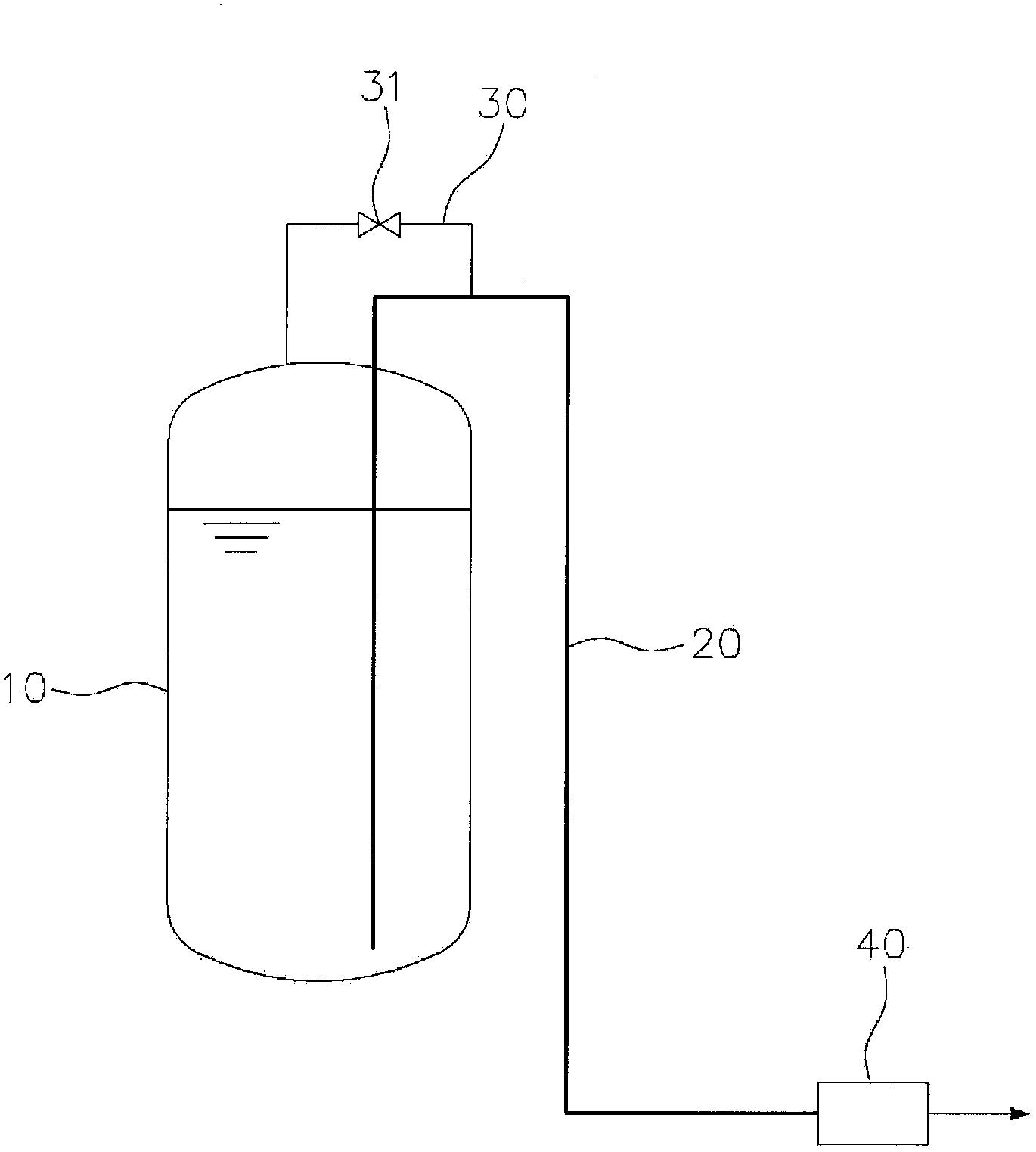
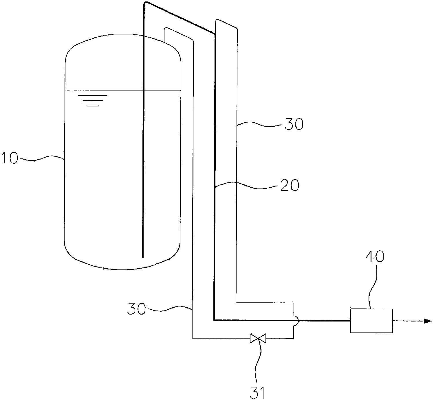
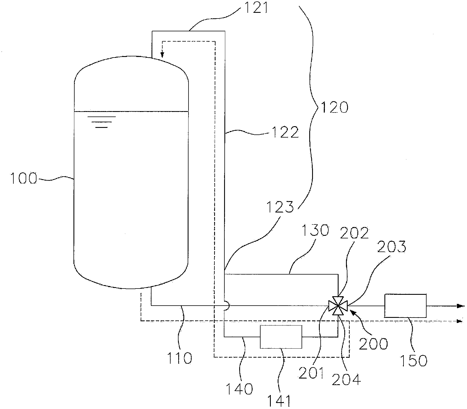

Image

  • Cryogenic storage tank system and auto flow path selector valve therefor
  • Cryogenic storage tank system and auto flow path selector valve therefor
  • Cryogenic storage tank system and auto flow path selector valve therefor

Examples


Embodiment Construction

[0048] Reference will now be made in detail to various embodiments of the invention, examples of which are depicted in the drawings and described hereinafter to enable those of ordinary skill in the art to which this invention pertains to The invention is easily implemented. However, the invention may be embodied in many different forms and should not be construed as limited to the embodiments set forth herein. In the following description of the present invention, when detailed descriptions of known functions and components incorporated herein make the subject matter of the present invention unclear, the descriptions will be omitted. Throughout this document, reference should be made to the drawings in which the same reference numerals and numerals are used throughout the different drawings to refer to the same or similar parts.

[0049] Throughout the specification, unless expressly stated to the contrary, the word "comprise" and variations thereof such as "comprises" or "c...


PUM


Abstract

A cryogenic storage tank system and an automatic flow path selector valve for the same, in which maintenance is more convenient, the length of pipes is minimized, and the pressure of liquefied gas in a gaseous phase inside a cryogenic storage tank is automatically adjusted.

Description

technical field [0001] The present invention relates to a technology related to a cryogenic storage tank system in which a gas having a very low boiling point, such as nitrogen or natural gas, can be stored, and more particularly, the present invention relates to a technology by which, The pressure of the liquefied gas in the gas phase within the cryogenic storage tank system can be automatically adjusted. Background technique [0002] When transporting or storing a gas with an extremely low boiling point, the gas is kept in a liquefied state, and for this purpose cryogenic storage tanks are utilized. Typically, cryogenic storage tanks are surrounded by insulating material that inhibits heat transfer. However, a part of the liquefied gas stored in the cryogenic storage tank evaporates naturally because it is impossible to completely prevent heat transfer. As a result, a certain part of the liquefied gas exists in a gas phase, which is called flash gas (hereinafter, referre...

Claims


Application Information

Patent Timeline
Patent Type & Authority Applications(China)
IPC IPC(8): F17C1/00F17C13/00F17C13/04F16K11/10
CPCF17C13/04F17C9/00F17C9/02F17C7/04F17C2201/032F17C2201/054F17C2203/03F17C2205/0382F17C2221/014F17C2221/033F17C2223/0161F17C2223/033F17C2223/043F17C2223/046F17C2225/0123F17C2225/035F17C2225/036F17C2227/0107F17C2227/0393
Inventor 全升采
Owner 全升采
Learn More