
Degassing and dehydrating miniature device for transformer oil

A technology for transformer oil and small devices, applied in measuring devices, instruments, measuring electrical variables, etc., can solve problems such as poor circulation of transformer oil, difficulty in sampling work, affecting the degassing and dehydration effect of transformer oil, etc., and shorten the working time , fast degassing speed, and the effect of improving work efficiency

Active Publication Date: 2014-07-02
PETROCHINA CO LTD
View PDF9 Cites 5 Cited by
  • Summary
  • Abstract
  • Description
  • Claims
  • Application Information

AI Technical Summary

Problems solved by technology

Before investigating the insulation performance of transformer oil in the laboratory, it is necessary to carry out degassing and dehydration treatment on transformer oil samples similar to industrial ones. Initially using the principle of industrial transformer oil degassing and dehydration treatment technology device, when the device is miniaturized, it is found that the gear When the pump is used as an oil circulation pump, a small amount of acetylene gas will be generated in the transformer oil; when a centrifugal pump or a magnetic vane pump is used, the transformer oil will not circulate smoothly in a high vacuum state, and a large amount of gas will be generated during the circulation process, which directly affects the transformer. The degassing and dehydration effect of oil makes it difficult to sample under vacuum

Method used


Image

  • Degassing and dehydrating miniature device for transformer oil

Examples


Embodiment Construction

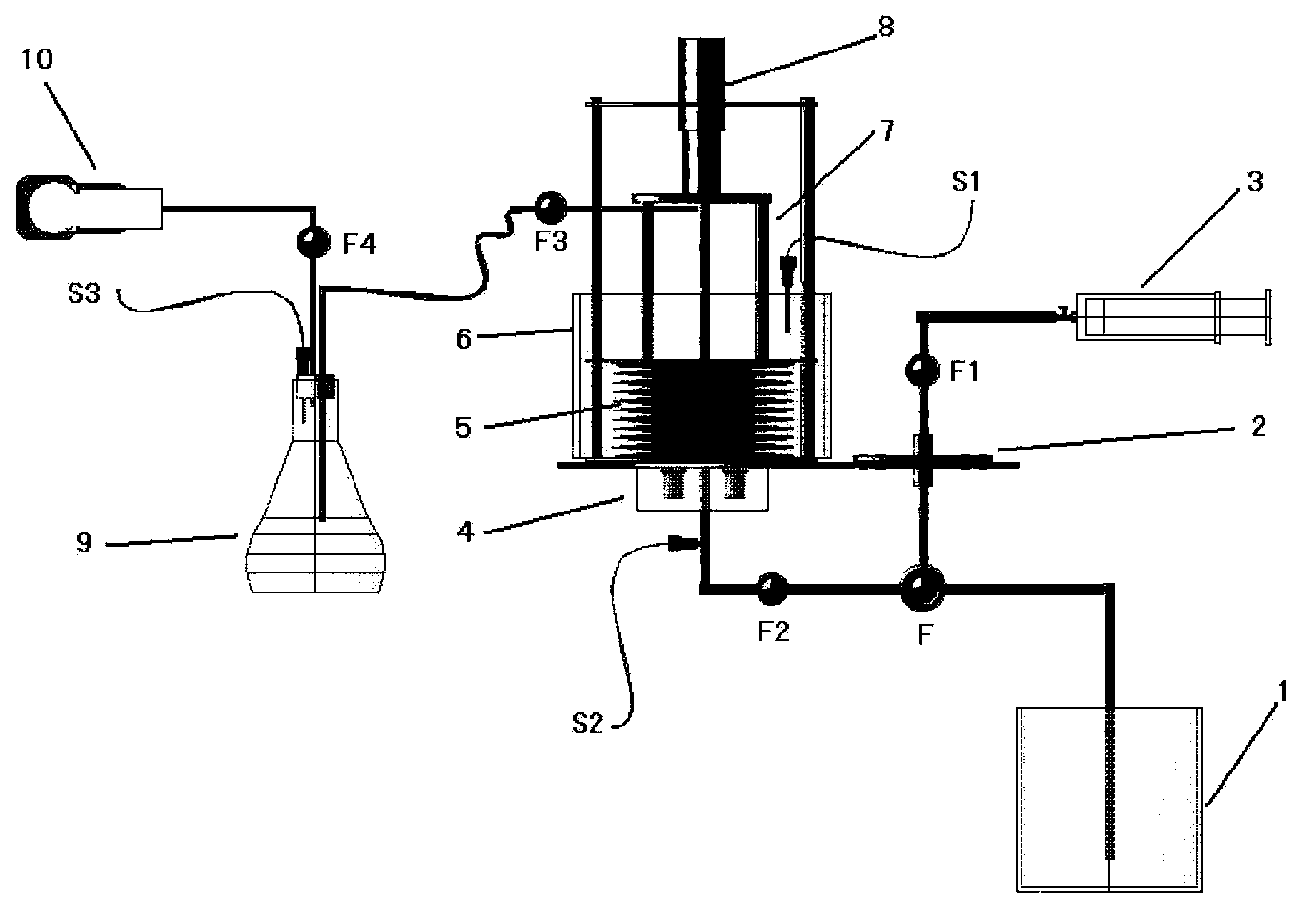
[0014] The small-sized device for degassing and dehydrating transformer oil according to the present invention includes an oil storage tank 1, a membrane filter 2, a sampler 3, an ultrasonic vibrator 4, a telescopic degassing tank 5, an air bath 6, a connecting rod 7, Electric reciprocating thruster 8, vacuum buffer tank 9, vacuum pump 10, temperature sensor S1, pressure sensor S2, vacuum pressure sensor S3, three-way solenoid valve F, single-way solenoid valve AF1, single-way solenoid valve BF2, and single-way solenoid valve CF3 , single-way solenoid valve DF4; oil storage tank 1 is connected to telescopic degassing tank 5 through three-way solenoid valve F and single-way solenoid valve BF2, and telescopic degassing tank 5 is connected to vacuum buffer tank 9 through single-way solenoid valve CF3 , the vacuum buffer tank 9 is connected to the vacuum pump 10 through the one-way electromagnetic valve DF4, the sampler 3 is connected to the three-way electromagnetic valve F throug...


PUM

PropertyMeasurementUnit
Apertureaaaaaaaaaa

Abstract

The invention relates to a degassing and dehydrating miniature device for transformer oil. An oil storage tank is connected with a telescopic degassing tank through a three-way electromagnetic valve and a single-pass electromagnetic value B. The telescopic degassing tank is connected with a vacuum buffer tank through a single-pass electromagnetic valve C. The vacuum buffer tank is connected with a vacuum pump through a single-pass electromagnetic valve D. A sampler is connected with the three-way electromagnetic valve through the single-pass electromagnetic valve A and a thin-film filter. An ultrasonic vibrator is fixed at the lower part of a base of the telescopic degassing tank. The telescopic degassing tank is placed in a temperature-controllable air bath. The upper part of the telescopic degassing tank is connected with an electrical repeated propeller through a connection rod. A pressure sensor is installed on a connection pipe of the telescopic degassing tank and the single-pass electronic valve B. A temperature sensor is installed in the air bath. A vacuum pressure sensor is installed on the vacuum buffer tank. The degassing and dehydrating miniature device for the transformer oil uses combination of the electrical repeated propeller, the telescopic degassing tank and the ultrasonic vibration to perform vacuum degassing and dehydration on samples so that degassing efficiency is improved and degassing speed is high.

Description

technical field [0001] The invention provides a small device for degassing and dehydrating a small amount of transformer oil under vacuum, and belongs to the technical field of laboratory transformer oil treatment. Background technique [0002] In order to improve the electric strength of the transformer oil and reduce the dielectric loss factor and other insulation performance indicators, the transformer oil must be treated before being injected into the equipment to remove the moisture, gas and impurities in the oil. Generally, the method of heating, vacuuming and fine filtration is widely used to remove the water, gas and impurities dissolved in the transformer oil. At present, two technologies are commonly used in industry: spray dehydration and degassing method and film dehydration and degassing method. The treated transformer oil is heated to about 50-70°C through a coarse oil filter and a heater, and is circulated to the dehydration by an oil pump. In the gas tank, t...

Claims


Application Information

Patent Timeline
IPC IPC(8): G01R31/20
Inventor 于会民马书杰张绮郭春梅王会娟王鹏
Owner PETROCHINA CO LTD
Learn More