

An Omnidirectional Terminal Antenna
A terminal antenna and feeder technology, applied in the directions of the antenna, electrical components, radiating element structure, etc., can solve the problems of difficult to achieve omnidirectional type, poor resonance characteristics, affecting the antenna bandwidth, etc., to reduce the size of the antenna and reduce the size. , the effect of broadening the resonance bandwidth
Inactive Publication Date: 2016-05-04
NINGBO CHENGDIAN TAIKE ELECTRONICS INFORMATION TECH DEV
View PDF8 Cites 0 Cited by
- Summary
- Abstract
- Description
- Claims
- Application Information
AI Technical Summary
Problems solved by technology
[0003] The current miniaturization technologies include meandering technology, short-circuit loading, lumped parameter loading, and increasing the dielectric constant and magnetic permeability of the substrate, etc., but the miniaturization of the antenna will affect the bandwidth of the antenna. Generally, the bandwidth will be narrowed. The resonance characteristics become worse, so the bandwidth problem needs to be considered
In addition, technologies such as meandering current and short-circuit loading are based on microstrip antenna technology, and its radiation has strong directionality. However, many mobile terminals require omnidirectional transceiver characteristics, so it is difficult to achieve omnidirectional
Method used
View moreImage
Smart ImageViewing Examples

Examples
Embodiment 2
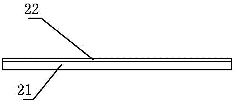
[0025] Embodiment 2: other parts are the same as the embodiment, the difference is that the reflector 2 is a PCB board, the feed end is the microstrip line 24 etched on the PCB board, and the vertex of the isosceles triangle substrate 1 is directly welded on the microstrip line 24. On the stripline 24 , the front copper clad layer and the reverse copper clad layer of the isosceles triangular substrate 1 are respectively connected to the microstrip line 24 .
Login to View More PUM
 Abstract
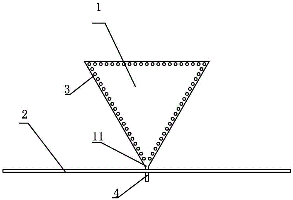
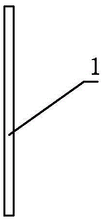
The invention discloses an omnidirectional terminal antenna. The omnidirectional terminal antenna comprises a radiating unit, a reflecting plate and a feed end and is characterized in that the radiating unit comprises a triangular substrate, one corner of the triangular substrate is supported on the reflecting plate as a supporting point, the triangular substrate perpendicularly stands on the reflecting plate, the front face and the back face of the triangular substrate are respectively provided with a copper cladding layer, plated through holes are evenly distributed in the periphery of the triangular substrate, and the copper cladding layer on the front face of the triangular substrate is connected with the copper cladding layer on the back face of the triangular substrate through the plated through holes. The omnidirectional terminal antenna has the advantages that a non-frequency-changing structure can be formed through a triangular resonance unit, the bandwidth can reach more than 30 percent, and the omnidirectional terminal antenna can be applied to a broadband system. Besides, the substrate integration waveguide technology is applied, the structural size of the antenna is reduced by 2 / 3, and omnidirectional radiation is achieved by omnidirectional terminal antenna.
Description
technical field [0001] The invention relates to a miniaturized antenna applied to a wireless terminal, in particular to a miniaturized PCB antenna with an omnidirectional pattern. Background technique [0002] With the rapid development of information technology and microelectronics technology, the miniaturization of electronic products has become a long-term development trend. In particular, the rapid development of wireless communication technology has further promoted the miniaturization of handheld mobile terminals and wearable products. The miniaturization technology of products is mainly based on the miniaturization of devices. Due to the development of microelectronics technology, the integration of devices is getting higher and higher, so the processing and transmission links of equipment are easy to realize miniaturization. The only major constraint is wireless electronics. The device for product miniaturization is the antenna. The structural size of the antenna i...
Claims
Login to View More Application Information
Patent Timeline
 Patent Type & Authority Patents(China)
IPC IPC(8): H01Q1/36H01Q19/10
Inventor 张海力杨瀚程田丹
Owner NINGBO CHENGDIAN TAIKE ELECTRONICS INFORMATION TECH DEV