Electro-osmosis ink jetting device
An inkjet device and electroosmosis technology, applied in printing and other directions, can solve problems such as complex drive system, unstable inkjet quality, uneven ink droplets and ink residue, etc., to expand the selection range, controllable inkjet quality, Avoid the effects of Joule heating
- Summary
- Abstract
- Description
- Claims
- Application Information
AI Technical Summary
Problems solved by technology
Method used
Image
Examples
Embodiment 1
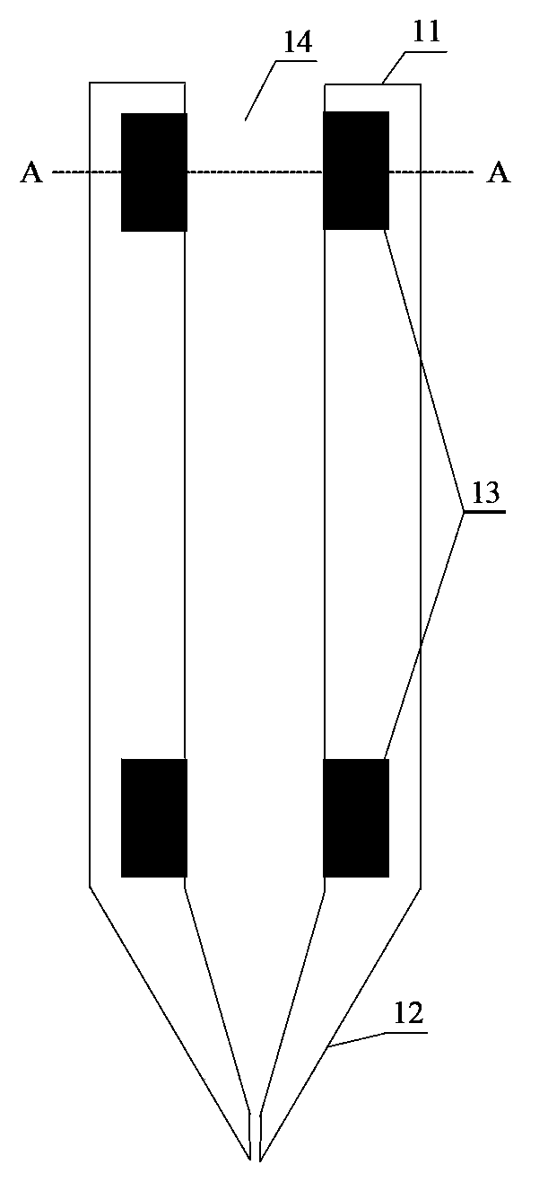
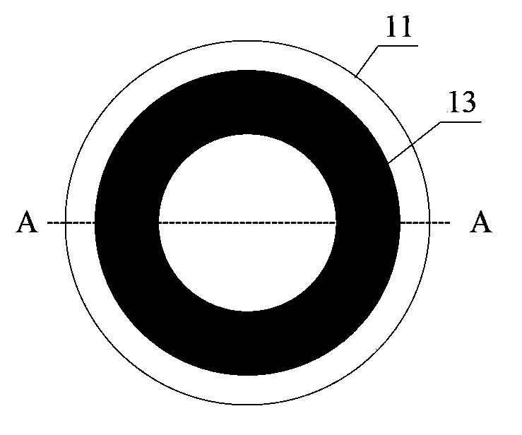
[0032] like figure 1 As shown, the electroosmotic inkjet device provided in this embodiment includes a microfluidic tube 11 , a nozzle 12 and two microelectrodes 13 . The micro-channel tube 11 is in the shape of a hollow cylinder, and its internal cavity is a micro-channel 14 for ink to flow through. One end of the micro-channel tube 11 is connected to an ink supply device (not shown in the figure), and the other end of the micro-channel tube 11 is provided with a nozzle 12 . The nozzle 12 has, for example, a tapered shape for ejecting ink droplets. The microelectrodes 13 are, for example, circular, such as figure 2 shown. The two microelectrodes 13 are respectively embedded on the inner side walls of the two ends of the microchannel tube 11 , so that the two microelectrodes 13 can directly contact the ink in the microchannel 14 . The material of the microchannel tube 11 and the nozzle 12 is an insulating material. In this embodiment, the material of the microchannel tub...
Embodiment 2
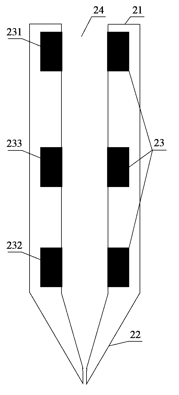
[0035] like image 3 As shown, the electroosmotic inkjet device provided in this embodiment includes a microfluidic tube 21 , a nozzle 22 and three microelectrodes 23 . The micro-channel tube 21 is in the shape of a hollow cylinder, and its internal cavity is a micro-channel 24 for ink to flow through. One end of the micro-channel tube 21 is connected to an ink supply device (not shown in the figure), and the other end of the micro-channel tube 21 is provided with a nozzle 22 . The nozzle 22 has, for example, a tapered shape for ejecting ink droplets. The microelectrode 23 has, for example, a circular shape. The first microelectrode 231 and the second microelectrode 232 are respectively embedded on the inner sidewalls at the two ends of the microchannel tube 21, and the third microelectrode 233 is embedded on the inner sidewall of the middle part of the microchannel tube 21, so that the three microelectrodes 23 can It is in direct contact with the ink in the micro-channel 2...
Embodiment 3
[0040] like Figure 4 , Figure 5 and Image 6As shown, the electroosmotic inkjet device provided in this embodiment includes a microfluidic tube 31 , a nozzle 32 , two microelectrodes 33 and a liner 35 . The microchannel tube 31 is in the shape of a hollow cylinder. One end of the micro-channel tube 31 is connected to an ink supply device (not shown in the figure), and the other end of the micro-channel tube 31 is provided with a nozzle 32 . The nozzle 32 has, for example, a tapered shape for ejecting ink droplets. The two microelectrodes 33 are respectively embedded on the inner side walls of the two ends of the microchannel tube 31 , so that the two microelectrodes 33 can directly contact the ink in the microchannel 34 . The lining 35 is embedded on the inner side wall of the microchannel tube 31 except for the two microelectrodes 33 . The microchannel tube 31 and the inner liner 35 can be separated or integrally formed. Microelectrodes 33 and lining 35 are provided w...
PUM
 Abstract
Description
Claims
Application Information
 - R&D
- Intellectual Property
- Life Sciences
- Materials
- Tech Scout
- Unparalleled Data Quality
- Higher Quality Content
- 60% Fewer Hallucinations
Browse by: Latest US Patents, China's latest patents, Technical Efficacy Thesaurus, Application Domain, Technology Topic, Popular Technical Reports.
© 2025 PatSnap. All rights reserved.Legal|Privacy policy|Modern Slavery Act Transparency Statement|Sitemap|About US| Contact US: help@patsnap.com


