Electroosmotic inkjet device

An inkjet device and electroosmotic technology, applied in printing and other directions, can solve the problems of complex drive system, unstable inkjet quality, uneven ink drop and ink residue, etc., to expand the selection range, controllable inkjet quality, Avoid the effects of Joule heating

Active Publication Date: 2016-01-13
TECHNICAL INST OF PHYSICS & CHEMISTRY - CHINESE ACAD OF SCI
View PDF6 Cites 0 Cited by
  • Summary
  • Abstract
  • Description
  • Claims
  • Application Information

AI Technical Summary

Problems solved by technology

However, there are obvious deficiencies in thermal bubble jet inkjet: on the one hand, the nozzle is often in a high temperature state, and the nozzle is frequently alternated between hot and cold, and the bubbles expand and shrink repeatedly, making the inkjet quality unstable, and the ink droplet size, ink droplet shape, The ejection speed and direction are not easy to control, and the inkjet device is easy to age, and the inkjet device needs to be repaired or replaced frequently; Slow, prone to uneven ink droplets and ink residue
However, piezoelectric inkjet requires a relatively complex drive system, complex structure, and the inkjet device is large in size, difficult to process, and difficult to repair after the nozzle is damaged or clogged

Method used


Image

  • Electroosmotic inkjet device
  • Electroosmotic inkjet device
  • Electroosmotic inkjet device

Examples


Embodiment 1

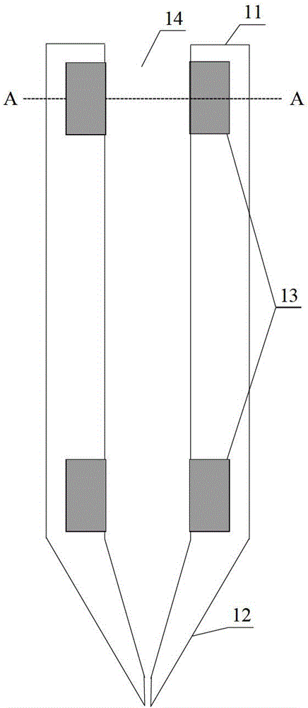
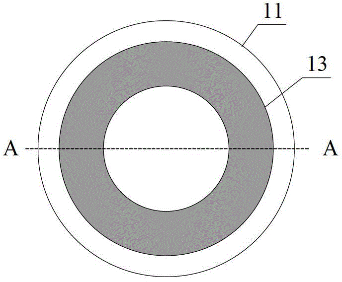
[0032] Such as figure 1 As shown, the electroosmotic inkjet device provided in this embodiment includes a microfluidic tube 11 , a nozzle 12 and two microelectrodes 13 . The micro-channel tube 11 is in the shape of a hollow cylinder, and its internal cavity is a micro-channel 14 for ink to flow through. One end of the micro-channel tube 11 is connected to an ink supply device (not shown in the figure), and the other end of the micro-channel tube 11 is provided with a nozzle 12 . The nozzle 12 has, for example, a tapered shape for ejecting ink droplets. The microelectrodes 13 are, for example, circular, such as figure 2 shown. The two microelectrodes 13 are respectively embedded on the inner side walls of the two ends of the microchannel tube 11 , so that the two microelectrodes 13 can directly contact the ink in the microchannel 14 . The material of the microchannel tube 11 and the nozzle 12 is an insulating material. In this embodiment, the material of the microchannel ...

Embodiment 2

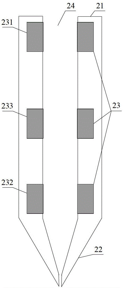
[0035] Such as image 3 As shown, the electroosmotic inkjet device provided in this embodiment includes a microfluidic tube 21 , a nozzle 22 and three microelectrodes 23 . The micro-channel tube 21 is in the shape of a hollow cylinder, and its internal cavity is a micro-channel 24 for ink to flow through. One end of the micro-channel tube 21 is connected to an ink supply device (not shown in the figure), and the other end of the micro-channel tube 21 is provided with a nozzle 22 . The nozzle 22 has, for example, a tapered shape for ejecting ink droplets. The microelectrode 23 has, for example, a circular shape. The first microelectrode 231 and the second microelectrode 232 are respectively embedded on the inner sidewalls at both ends of the microchannel tube 21, and the third microelectrode 233 is embedded on the inner sidewall of the middle part of the microchannel tube 21, so that the three microelectrodes 23 can It is in direct contact with the ink in the micro-channel 2...

Embodiment 3

[0040] Such as Figure 4 , Figure 5 with Image 6As shown, the electroosmotic inkjet device provided in this embodiment includes a microfluidic tube 31 , a nozzle 32 , two microelectrodes 33 and a liner 35 . The microchannel tube 31 is in the shape of a hollow cylinder. One end of the micro-channel tube 31 is connected to an ink supply device (not shown in the figure), and the other end of the micro-channel tube 31 is provided with a nozzle 32 . The nozzle 32 has, for example, a tapered shape for ejecting ink droplets. The two microelectrodes 33 are respectively embedded on the inner side walls of the two ends of the microchannel tube 31 , so that the two microelectrodes 33 can directly contact the ink in the microchannel 34 . The lining 35 is embedded on the inner side wall of the microchannel tube 31 except for the two microelectrodes 33 . The microchannel tube 31 and the inner liner 35 can be separated or integrally formed. Microelectrodes 33 and lining 35 are provid...


PUM


Abstract

The invention provides an electro-osmosis ink jetting device which comprises a micro-channel pipe, a spray nozzle and micro-electrodes. The micro-channel pipe is a hollow cylinder, an inner cavity of the micro-channel pipe is a micro-channel for ink to flow through, one end of the micro-channel pipe is connected with an ink supply device, the other end of the micro-channel pipe is provided with the spraying nozzle, the inner side walls at the two ends of the micro-channel pipe are respectively provided with one micro-electrode in an embedded mode, and an electric field formed between the two micro-electrodes can drive ink in the micro-channel to move in the direction of the spraying nozzle. According to the ink jetting device, ink jetting quality is high and controllable; a complicated drive system is not needed, the structure is simple, the size is small, and the ink jetting device is easy to process and maintain; the inner surface of the micro-channel pipe, the inner surface of the spraying nozzle and the inner surfaces of the micro-electrodes of the ink jetting device are provided with insulating layers, joule heat can be avoided, the selection range of materials of the micro-electrodes is widened, and reduction of cost is facilitated.

Description

technical field [0001] The invention relates to the technical field of inkjet devices, in particular to an electroosmotic inkjet device. Background technique [0002] The inkjet device is the core component of an inkjet printing device or an inkjet writing pen. The inkjet device is used to drive the flow of ink droplets and eject the ink droplets precisely onto the surface of the printing or writing medium. The inkjet quality of an inkjet device, such as ink droplet size, ink droplet shape, ink droplet ejection speed and direction, etc., depends on its inkjet method. Common inkjet methods include thermal bubble inkjet (Thermalbubble inkjet) and piezoelectric inkjet (Piezoelectric inkjet). [0003] Thermal bubble jetting activates the ink by heating to generate bubbles, and the expansion of the bubbles drives the ink to flow in the micro-channel, and ejects ink droplets through the nozzles to the surface of the printing or writing medium to form ink marks. Thermal bubble j...

Claims


Application Information

Patent Timeline
Patent Type & Authority Patents(China)
IPC IPC(8): B41J2/01B41J2/045
Inventor 桂林高猛刘静
Owner TECHNICAL INST OF PHYSICS & CHEMISTRY - CHINESE ACAD OF SCI
Why Eureka
Try Eureka