Energy-saving tunnel reduction kiln

A tunnel and kiln car technology, applied in the field of roasting equipment and smelting, can solve the problems of changing the one-way single-lane car entry mode, difficult to control pressure and atmosphere, and large floor space, achieving small footprint, flexible location selection, The effect of low operating costs

Inactive Publication Date: 2014-07-09
SONGYANG COUNTY ZHONGQI ENVIRONMENTAL ENGCO
View PDF5 Cites 6 Cited by
  • Summary
  • Abstract
  • Description
  • Claims
  • Application Information

AI Technical Summary

Problems solved by technology

Another example is that after the kiln is extended, the pressure and atmosphere in the kiln are not easy to control, and it is very difficult to operate
To solve these problems, on the one hand, it is necessary to increase the fire path between the refractory tanks. Due to the addition of fire paths on a single kiln car, there will be unstable factors when stacking refractory tanks, and it is easy to pour the tanks; on the other hand, it is necessary to change the one-way single-lane entry mode
At the same time, the current tunnel kiln generally adopts a three-zone division model, namely, the preheating section, the reduction section and the cooling section. Auxiliary facilities need to be built outside the kiln, such as tow lanes, return lines, and loading and unloading areas. Such a kiln body structure not only exists It occupies a large area, and in order to save energy, it is necessary to install a waste heat recovery device on the kiln body to recover and reuse the waste heat in the cooling section of the kiln body

Method used


Image

  • Energy-saving tunnel reduction kiln

Examples


Embodiment 1

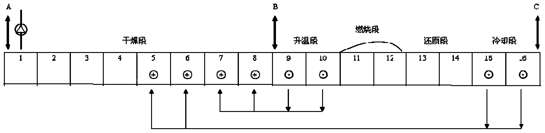
[0029] as attached figure 1 As shown, an energy-saving tunnel reduction kiln is built, wherein the tunnel reduction kiln is sequentially set up as a drying section, a heating section, a combustion section, a reducing section, and a cooling section; there is a ventilation outlet at the top of the entrance of the drying section, and the entrance of the heating section There is a heat source inlet at the top, and an air inlet is opened at the top of the outlet of the cooling section; the bottom of the cooling section communicates with the bottom of the middle position of the drying section, and the bottom of the heating section communicates with the bottom near the exit of the drying section. The length of the drying section is equivalent to the total length of the heating section, combustion section, reduction section and cooling section.

[0030] A track is laid at the bottom of the reduction kiln in the energy-saving tunnel, and a kiln car is loaded on the track, and coal powd...


PUM


Abstract

The invention relates to a smelting and roasting device and particularly relates to an energy-saving tunnel reduction kiln for both combustion and reduction. The energy-saving tunnel reduction kiln is characterized in that a drying section, a heating section, a combustion section, a reduction section and a cooling section are orderly arranged in the tunnel reduction kiln; the sections have different functions; a ventilation outlet is formed in the top of the inlet of the drying section, a heat source inlet is formed in the top of the inlet of the heating section, and an air inlet is formed in the top of the outlet of the cooling section; the bottom of the cooling section is communicated with the bottom of the middle position of the drying section, and the bottom of the heating section is communicated with the bottom of the drying section in a position near the outlet. The energy-saving tunnel reduction kiln has the advantages of energy saving, no requirement on a drying place for molded materials, low noise and the like.

Description

technical field [0001] The invention relates to a smelting and roasting device, in particular to an energy-saving tunnel reduction kiln with both combustion and reduction. Background technique [0002] With the continuous development of science and technology, in order to meet the needs of the large-scale development of direct reduction iron tunnel kiln production, the development trend of direct reduction tunnel kiln is that the kiln is long and wide. However, simply lengthening and widening is difficult to solve problems in actual production, and there are many disadvantages. For example, after the kiln is widened, the kiln car will also be widened accordingly, and the density of the refractory tank on the kiln car will increase, so the sponge iron in the middle of the kiln car will not be fully reduced and the phenomenon will appear. Another example is that after the kiln is extended, the pressure and atmosphere in the kiln are not easy to control, and it is very difficu...

Claims


Application Information

Patent Timeline
Patent Type & Authority Applications(China)
IPC IPC(8): F27B9/02F27B9/26
Inventor 陈启松杨辉陈宇青徐斌陈方洁
Owner SONGYANG COUNTY ZHONGQI ENVIRONMENTAL ENGCO
Why Eureka
Try Eureka