Multifunctional wear test device for material wear analysis

A wear test, multi-functional technology, applied in the direction of testing wear resistance, etc., can solve the problems of increasing test cost and site requirements, function selection, increasing cost, etc., to achieve cost reduction, convenient interface connection, and speed. tune effect

Active Publication Date: 2014-07-09
ZHEJIANG UNIV
View PDF6 Cites 15 Cited by
  • Summary
  • Abstract
  • Description
  • Claims
  • Application Information

AI Technical Summary

Problems solved by technology

The current multi-functional wear testing machine integrates various modules together, and adds modules such as electronic control measurement, which are bulky and costly. It is impossible to choose the function when purchasing. If multiple groups of parallel tests are to be carried out, a whole set of machines needs to be purchased. Greatly increase the cost of the test and the demand for the site; if a single-function testing machine is used, although the unit cost is low, when the test requirements change and the wear mode needs to be changed, the whole machine needs to be purchased again, which also increases the cost ; So far, there is no modularized multi-functional wear testing machine that can be freely manually disassembled and can perform multiple tests in parallel according to requirements.

Method used


Image

  • Multifunctional wear test device for material wear analysis
  • Multifunctional wear test device for material wear analysis
  • Multifunctional wear test device for material wear analysis

Examples


Embodiment Construction

[0033] The present invention will be further described below in conjunction with the accompanying drawings and embodiments.

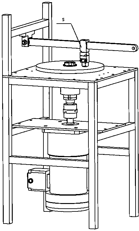
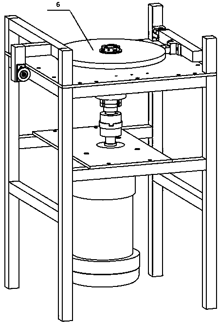
[0034] refer to Figure 1-Figure 7, a multifunctional wear test device for material wear analysis, comprising a frame 1, an adjustable speed power system 2, a spindle positioning mechanism 3, the adjustable speed power system 2 is fixed on the frame 1, including Motor and frequency converter; the main shaft positioning mechanism 3 is connected to the adjustable speed power system 2, including a positioning mechanism 3-2 and a main shaft 3-1, and the lower end of the main shaft 3-1 is connected to the motor through a coupling The multifunctional wear test device also includes a reciprocating wear module 4, a pin-on-disk wear module 5, and a ring block wear module 6; the reciprocating wear module 4 is installed on the frame 1, including a cam 4-1, Stroke amplification mechanism 4-2, friction block 4-6, friction platform 4-5, friction platform support dev...


PUM


Abstract

The invention discloses a multifunctional wear test device for material wear analysis. The multifunctional wear test device comprises a frame, speed-regulated power systems and spindle positioning mechanisms, wherein each speed-regulated power system comprises a motor and a frequency converter; totally Q groups of speed-regulated power systems are arranged and are fixed on the frame; Q is a natural number and is more than or equal to 1; totally Q groups of spindle positioning mechanisms are arranged and correspond to the speed-regulated power systems one by one; each spindle positioning mechanism comprises a positioning mechanism and a spindle; the lower end of the spindle is connected with the motor through a coupler. The multifunctional wear test device also comprises R groups of reciprocating wear modules, S groups of pin disc type wear modules and T groups of ring block type wear modules, wherein R, S and T are integers, R is more than or equal to 0, S is more than or equal to 0, T is more than or equal to 0, and R+S+T is equal to Q. Disassembly can be manually performed by using each module, the volume of the machine is greatly reduced, joints among the modules are conveniently connected, only the needed modules are needed to be processed during processing and use, and the cost is greatly reduced.

Description

Technical field [0001] The invention design the field of friction and wear test machine, especially a multi -function wear test machine used for wear. technical background [0002] When the two -contact objects, when the relative motion or relative movement trend under the action of external forces, the cutting resistance generated on the contact surface becomes friction. This impedance phenomenon is called friction.The friction effect is often accompanied by the gradual disappearance of surface materials. This is wear. Dason is one of the three main faults of the material. It causes the losses very huge. [0003] According to the motion of the motion, the form of motion can be divided into sliding friction and rolling friction. In the laboratory, the main forms of skating friction are selling, ring blocks, and reciprocated.The current multifunctional wear test machine integrates each module and adds modules such as electrical control measurement. It has a large volume and high c...

Claims


Application Information

Patent Timeline
Patent Type & Authority Applications(China)
IPC IPC(8): G01N3/56
Inventor 顾大强阎文舟苗慧杰叶陈吉宋曼
Owner ZHEJIANG UNIV
Why Eureka
Try Eureka