
Display device

A technology for display devices and display panels, which is applied to lighting devices, fixed lighting devices, components of lighting devices, etc., and can solve problems such as low brightness ratio, image quality degradation, and brightness ratio reduction

Active Publication Date: 2014-07-09
LG DISPLAY CO LTD
View PDF7 Cites 4 Cited by
  • Summary
  • Abstract
  • Description
  • Claims
  • Application Information

AI Technical Summary

Problems solved by technology

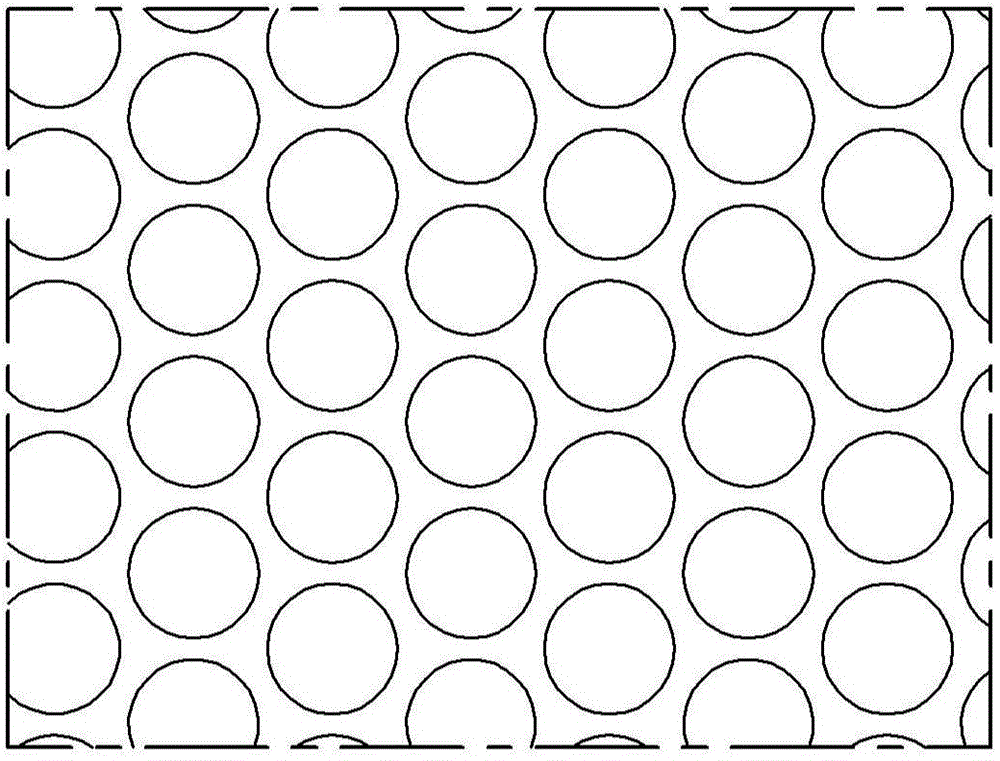
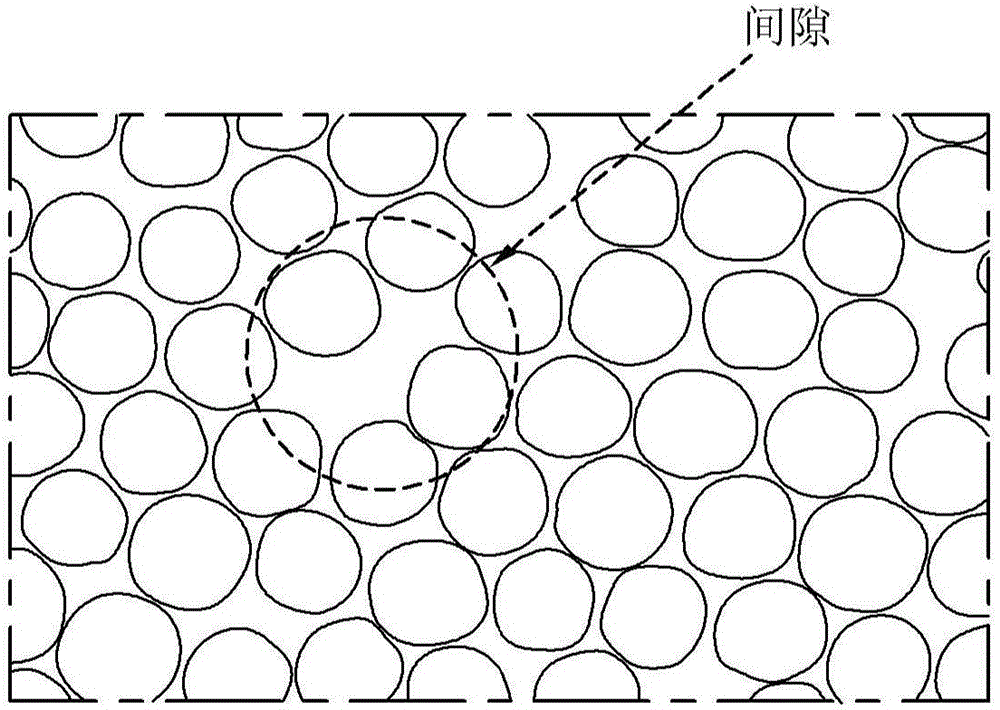
However, if figure 2 Illustratively shown, regularly placed lenses can cause speckles in large gaps that are perceived as sparkling spots, which can lead to degradation of image quality and reduction in brightness ratio due to low fill factor
[0006] As mentioned above, a fixed-shape microlens film results in moiré generation, while a non-fixed-shape microlens film results in generation of flickering spots due to large gaps between lenses and low luminance ratio due to low fill factor.

Method used


Image

  • Display device
  • Display device
  • Display device

Examples


Embodiment approach

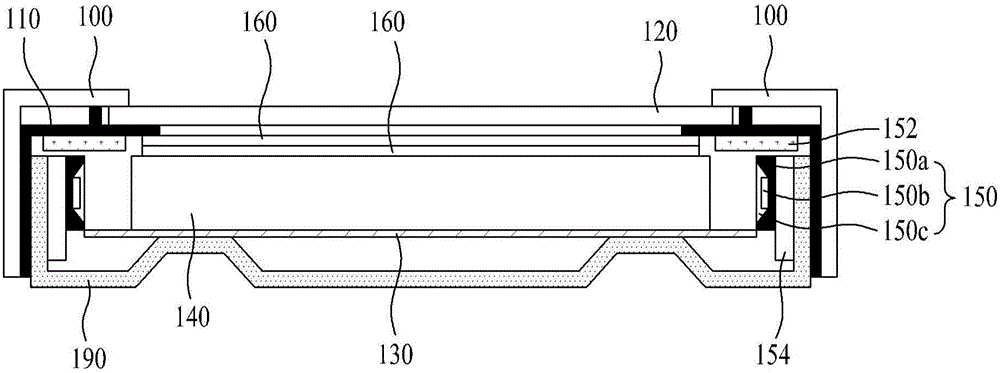
[0050] image 3 is a cross-sectional view showing the display device according to the first embodiment of the present invention.

[0051] refer to image 3 , The display device according to the first embodiment of the present invention includes a display panel displaying images, a backlight unit supplying light to the display panel, a mold frame (mold frame) 110 provided with the display panel, coupled to the mold frame 110 to surround the display panel The upper case 100 at the edge of the panel and the lower cover 190 on which the backlight unit is mounted.

[0052] For example, the display panel may include a liquid crystal display panel or an organic field emission display panel. In the following description, a liquid crystal display panel will be described as an example.

[0053] A liquid crystal display panel denoted by reference numeral 120 includes a lower substrate provided with thin film transistors connected to gate lines and data lines, an upper substrate provid...


PUM

PropertyMeasurementUnit
sizeaaaaaaaaaa
sizeaaaaaaaaaa
sizeaaaaaaaaaa

Abstract

Disclosed is a display device including a micro-lens film which has a high fill-factor and a high luminance ratio and prevents generation of moire. The display device comprises: a display panel configured to display an image; a plurality of Light Emitting Diodes (LEDs) configured to generate light to supply light to the display panel; a light guide panel configured to guide light to the display panel; and a micro-lens film including a base film that concentrates and diffuses light emitted from the light guide panel, a lens unit at an upper surface of the base film, and a back-coating film at a lower surface of the base film. The lens unit includes unit block groups randomly arranged at the upper surface of the base film, each unit block group containing randomly arranged fixed-shape lenses having different sizes, and micro-beads randomly formed on surfaces of the fixed-shape lenses.

Description

technical field [0001] The present invention relates to a display device including a microlens film, and in particular, to a display device including a microlens film having a high fill-factor and a high luminance ratio and preventing moiré from being generated. Background technique [0002] The liquid crystal display device displays images by adjusting the light transmittance of dielectrically anisotropic liquid crystals using an electric field. A typical liquid crystal display device includes a liquid crystal display panel composed of a thin film transistor substrate and a color filter substrate coupled to face each other, a backlight unit configured to emit light to the liquid crystal display panel, and a driving circuit configured to drive the liquid crystal display panel. [0003] The above-mentioned backlight unit includes a light source configured to generate light, a light guide plate configured to guide light so as to emit light toward the liquid crystal display pan...

Claims


Application Information

Patent Timeline
Patent Type & Authority Applications(China)
IPC IPC(8): G02F1/13357F21S8/00F21V13/02F21Y101/02
CPCG02F1/133615G02B5/0221G02B6/0053G02B5/0278G02F1/133526H01L33/58H01L27/156
Inventor 李相贤文源铎金善雄金宝罗韩相大昌秀真
Owner LG DISPLAY CO LTD
Learn More