Resistance trigger type vacuum arc ion source device

A trigger type, vacuum arc technology, applied in the field of ion source, can solve the problems of complex power source, increase the complexity of ion source structure, volume weight and cost, and achieve the goal of improving reliability, increasing design difficulty and reducing contact resistance. Effect

Inactive Publication Date: 2014-07-09
INST OF FLUID PHYSICS CHINA ACAD OF ENG PHYSICS
View PDF9 Cites 2 Cited by
  • Summary
  • Abstract
  • Description
  • Claims
  • Application Information

AI Technical Summary

Problems solved by technology

At present, the trigger method of high-voltage surface discharge is generally used, but this method requires two sets of power sources to supply power, one for the cathode-anode, and one for the trigger electrode. An extra power system will increase the structure of the ion source. degree, volumetric weight and cost, or complexity of the power source

Method used


Image

  • Resistance trigger type vacuum arc ion source device
  • Resistance trigger type vacuum arc ion source device
  • Resistance trigger type vacuum arc ion source device

Examples


Embodiment 1

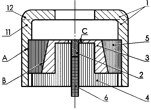
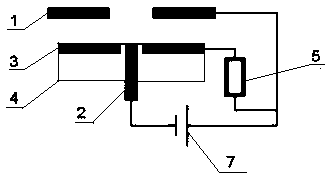
[0029] Such as figure 1As shown, the resistance-triggered vacuum arc ion source device includes an anode 1, a cathode 2, a trigger electrode 3, a cathode-trigger electrode insulator 4, a trigger resistor 5, and a cathode fixed conductive joint 6 connected to the lower end of the cathode 2. The above-mentioned anode 1 It consists of a hollow cylindrical first part of the anode 11 and a ring-shaped anode 12 connected to the upper end of the anode support 11. The above-mentioned trigger resistor 5, trigger electrode 3, cathode-trigger electrode insulator 4 and cathode 2 are arranged in sequence from outside to inside. In the anode support 11, the outer edge of the ring-shaped anode 12 is connected to the upper end of the anode support 11. In practical applications, the outer edge of the ring-shaped anode 12 and the anode support 11 are preferably made of the same material. The anode support 11 is also Can be discharged with cathode 2. The cathode fixing conductive joint 6 has tw...

Embodiment 2

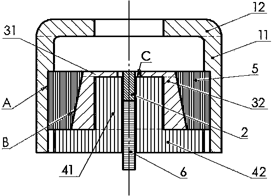
[0034] Such as figure 2 As shown, this embodiment is further improved on the basis of Embodiment 1. The above-mentioned cathode 2 and cathode fixed conductive joint 6 are both cylindrical, which are arranged on the central axis of the anode 1, and the above-mentioned cathode-trigger electrode insulating member 4 is covered Outside the cathode 2 and the cathode fixed conductive joint 6, and the upper end surface of the cathode-trigger insulator 4 is lower than the upper end surface of the cathode 2;

[0035] The above-mentioned trigger pole 3 is composed of a trigger pole support 32 coated on the outside of the cathode-trigger pole insulator 4 and a ring-shaped trigger pole 31 connected to the upper end of the trigger pole support 32. The trigger pole support 32 and the ring-shaped trigger pole 31 are also preferably The same material is integrally formed, the lower end surface of the annular trigger electrode 31 is also connected to the upper end surface of the cathode-trigge...

Embodiment 3

[0040] On the basis of Embodiment 2, in this embodiment, the cathode-trigger insulator 4 is composed of a first insulator 41 and a second insulator 42 located at the lower end of the first insulator 41, the first insulator 41 and the second insulator The insulators 42 are all hollow cylinders with the same inner diameter and coincident central axes, and the outer diameter of the first insulator 41 is smaller than that of the second insulator 42; the first insulator 41 and the second insulator 42 are preferably integrally manufactured from the same material , the inner peripheral surface of the first trigger pole 32 is connected to the outer peripheral surface of the first insulator 41, the above-mentioned annular trigger pole 31 is connected to the upper end of the first insulator 41; the lower end surface of the trigger resistor 5 and the trigger pole 3 are connected on the upper end surface of the second insulating member 42 .

[0041] In this embodiment, the inner periphera...


PUM

PropertyMeasurementUnit
Resistanceaaaaaaaaaa

Abstract

The invention discloses a resistance trigger type vacuum arc ion source device. The resistance trigger type vacuum arc ion source device comprises a positive electrode (1), a negative electrode (2), a trigger electrode (3), a negative electrode-trigger electrode insulator (4), a trigger resistor (5) and a negative electrode fixing conductive connector (6) connected to the lower end of the negative electrode (2), the positive electrode (1) is composed of a hollow cylindrical positive electrode supporting body (11) and an annular positive electrode (12) connected to the upper end of the positive electrode supporting body (11), and the trigger resistor (5), the trigger electrode (3), the negative electrode-trigger electrode insulator (4) and the negative electrode (2) are arranged in the positive electrode supporting body (11) from exterior to interior in sequence. The trigger resistor is arranged in the vacuum arc ion source device, the structure is compact, the size is small, the installing space is saved, the electrical contact and insulating reliability are guaranteed, and distribution parameters can be effectively improved.

Description

technical field [0001] The invention relates to the technical field of ion sources, in particular to a resistance-triggered vacuum arc ion source device. Background technique [0002] An ion source is a device that generates ions, and is one of the most important components in applications such as ion implantation and ion accelerators. Triggered vacuum arc ion source is a form of vacuum arc ion source that can achieve more intense discharge, higher current intensity and more complete ionization. [0003] At present, the methods of generating vacuum arc include high-voltage vacuum breakdown, high-voltage surface discharge, laser triggering, low-voltage arc starting, etc. The triggering mode of vacuum arc determines whether the ion source can be successfully triggered and then works, and also determines the engineering realization of the ion source device. Difficulty and reliability of work. At present, the trigger method of high-voltage surface discharge is generally used, ...

Claims


Application Information

Patent Timeline
IPC IPC(8): H01J37/08
Inventor 彭宇飞蓝朝晖龙继东杨振郑乐董攀李杰何佳龙王韬
Owner INST OF FLUID PHYSICS CHINA ACAD OF ENG PHYSICS
Why Eureka
Try Eureka