Humidifier for fuel cells and fuel cell stack with humidifier

A fuel cell and humidifier technology, applied in the direction of fuel cells, fuel cell additives, fuel cell grouping, etc., can solve problems such as unsatisfactory humidification effects, and achieve the effects of saving manufacturing costs, reducing costs, and low material costs

Active Publication Date: 2014-07-09
顺风恒劲氢能源发展(上海)有限公司
View PDF6 Cites 23 Cited by
  • Summary
  • Abstract
  • Description
  • Claims
  • Application Information

AI Technical Summary

Problems solved by technology

This humidifier minimizes the pressure drop in the humidifier, thus ensuring the life of the exchange diaphragm, but its humidification effect is not ideal

Method used


Image

  • Humidifier for fuel cells and fuel cell stack with humidifier
  • Humidifier for fuel cells and fuel cell stack with humidifier
  • Humidifier for fuel cells and fuel cell stack with humidifier

Examples


Embodiment 1

[0027] air self-humidification

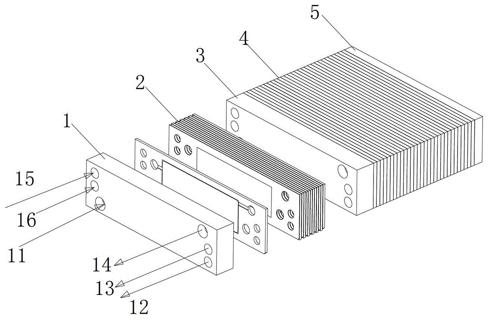
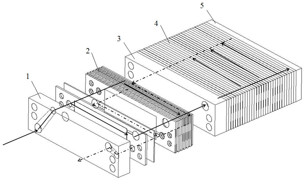
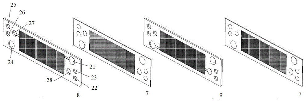
[0028] Such as Figure 1-2 As shown, a humidifier for a fuel cell and a fuel cell stack with the humidifier, the fuel cell includes a front end plate 1, a humidifier 2, a rear end plate 3, a stack 4 and a bottom plate 5 connected in sequence, and the humidifier It is composed of a number of humidification units 6 and humidification membrane components 7 interposed between the front end plate and the rear end plate. The humidification unit 6 is composed of a dry panel 8, a humidification membrane component 7 and a wet panel 9 in sequence. The two humidification units A humidification membrane module 7 (such as image 3 As shown), the front end plate 1, rear end plate 3, dry panel 8 and wet panel 9 are provided with three inlets and three outlets: oxidant inlet 21, fuel inlet 25, coolant inlet 26, oxidizer outlet 24, fuel outlet 22, Coolant outlet 23, also set up two inlet and outlet branch ports on the dry panel and the wet panel, air intake b...

Embodiment 2

[0037] Hydrogen Humidification

[0038] The structure of the electric stack is as in Example 1, a humidifier is set, only the total hydrogen inlet is exchanged with the total air inlet, and the total hydrogen outlet is exchanged with the total air outlet, the inlet branch on the humidifier The port is connected to the total hydrogen gas inlet on the front panel, and the oxidant inlet 21 on the dry panel 8 is used as the hydrogen gas inlet. All the other are with embodiment 1.

Embodiment 3

[0040] Simultaneous humidification of air and hydrogen

[0041] Such as image 3 As shown, the gas to be humidified is hydrogen and air, and there are two humidifiers, one as a hydrogen humidifier 28 and the other as an air humidifier 29 .

[0042] Described hydrogen humidifier 28 is identical with the humidifying unit structure of air humidifier 29, only will be used as the position of total hydrogen gas inlet 15 on hydrogen humidifier 28, as total air inlet 11 on air humidifier 29, And the position where the hydrogen humidifier 28 is used as the total hydrogen gas outlet 12 is used as the total air outlet 14 on the air humidifier 29 .

[0043] After the hydrogen flows in from the front plate, it flows in from the inlet branch of the hydrogen humidifier for humidification, and then flows into the power stack through the total hydrogen inlet set on the air humidifier to react; the air flows in from the front plate and passes through the hydrogen humidifier. The set total air...


PUM


Abstract

The invention relates to a humidifier for fuel cells and a fuel cell stack with the humidifier. The humidifier is formed by overlaying multiple humidifying units and humidifying membrane assemblies; each humidifying unit is formed by successively overlaying a dry panel, one humidifying membrane assembly and a wet panel, and one humidifying membrane assembly is arranged between two humidifying units in a clamping manner; each humidifying membrane assembly, each dry panel and each wet panel all are provided with three inlets and three outlets, and each dry panel and each wet panel both are provided with an air branch inlet and an air branch outlet; and the fuel cell comprises successively connected front-end plate, humidifier, rear-end plate, cell stack and bottom plate, and the front-end plate, the rear-end plate and the cell stack are all provided with three inlets and three outlets, wherein the three inlets and the three outlets comprise a master hydrogen inlet, a master air inlet, a master water inlet, a master hydrogen outlet, a master air outlet and a master water outlet. Compared with the prior art, the humidifier for fuel cells has the advantages of being capable of effectively humidifying air, improving service life, simplifying installation program, improving efficiency, reducing cost and the like.

Description

technical field [0001] The invention belongs to the technical field of fuel cells, in particular to a humidifier for fuel cells and a fuel cell stack with the humidifier. Background technique [0002] A fuel cell is a device that directly converts the chemical energy of hydrogen and oxygen into electrical energy through an electrode reaction. A fuel cell is generally constructed of a plurality of cells, each cell comprising two electrodes (anode and cathode) separated by an electrolyte element and assembled in series with each other to form a fuel cell stack. The electrochemical reaction is achieved by supplying the appropriate reactants to each electrode, ie fuel to one electrode and oxidant to the other, creating a potential difference between the electrodes and thereby generating electrical energy. [0003] Proton exchange membrane fuel cell is a kind of fuel cell. Proton exchange membrane fuel cell (PEMFC) is widely used in the field of portable computer, motor vehicle ...

Claims


Application Information

Patent Timeline
Patent Type & Authority Applications(China)
IPC IPC(8): H01M8/04H01M8/24H01M8/04119H01M8/2457
CPCH01M8/04126H01M8/04141H01M8/2465H01M2008/1095Y02E60/50Y02P70/50
Inventor 高勇
Owner 顺风恒劲氢能源发展(上海)有限公司
Why Eureka
Try Eureka