

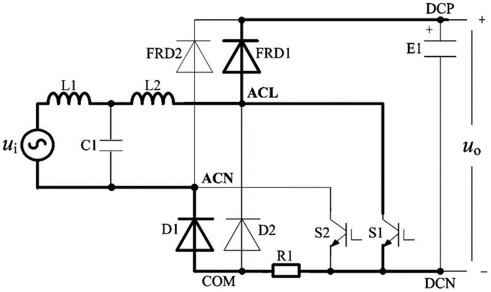
Common-anode half-bridge power factor correction circuit
A technology of power factor correction and unity power factor, which is applied in the field of power electronics conversion, can solve problems such as difficult heat dissipation of power devices, installation of boost inductors on the board, cost problems, difficulty in detecting inductor current, and low support power levels, etc., to achieve The effect of reducing design difficulty, reducing size, and using a small number of devices
- Summary
- Abstract
- Description
- Claims
- Application Information
AI Technical Summary
Problems solved by technology
Method used
Image

Examples
Embodiment Construction
[0022] The present invention will be described in detail below in conjunction with specific embodiments. The following examples will help those skilled in the art to further understand the present invention, but do not limit the present invention in any form. It should be noted that those skilled in the art can make several modifications and improvements without departing from the concept of the present invention. These all belong to the protection scope of the present invention.
[0023] Such as figure 1 As shown, this embodiment provides a common anode half-bridge power factor correction circuit, which includes a first chopping unit and a second chopping unit, and the first chopping unit is used to complete unit power factor correction in the negative half cycle of the grid voltage. phase AC-DC conversion, and output a stable DC voltage; the second chopping unit is used to complete the unit power factor single-phase AC-DC conversion in the positive half cycle of the grid v...
PUM
 Abstract
Description
Claims
Application Information