Energy-saving non-resistance check valve
A check valve, non-resistance technology, applied in the field of machinery, can solve the problems of not suitable for conveying medium with particles and easy to deposit, large fluid resistance of check valve, high energy consumption, convenient online replacement, preventing backflow of conveying medium, Reduce the effect of damage
- Summary
- Abstract
- Description
- Claims
- Application Information
AI Technical Summary
Problems solved by technology
Method used
Image
Examples
Embodiment 1
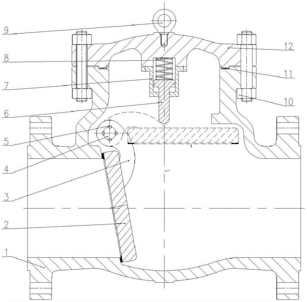
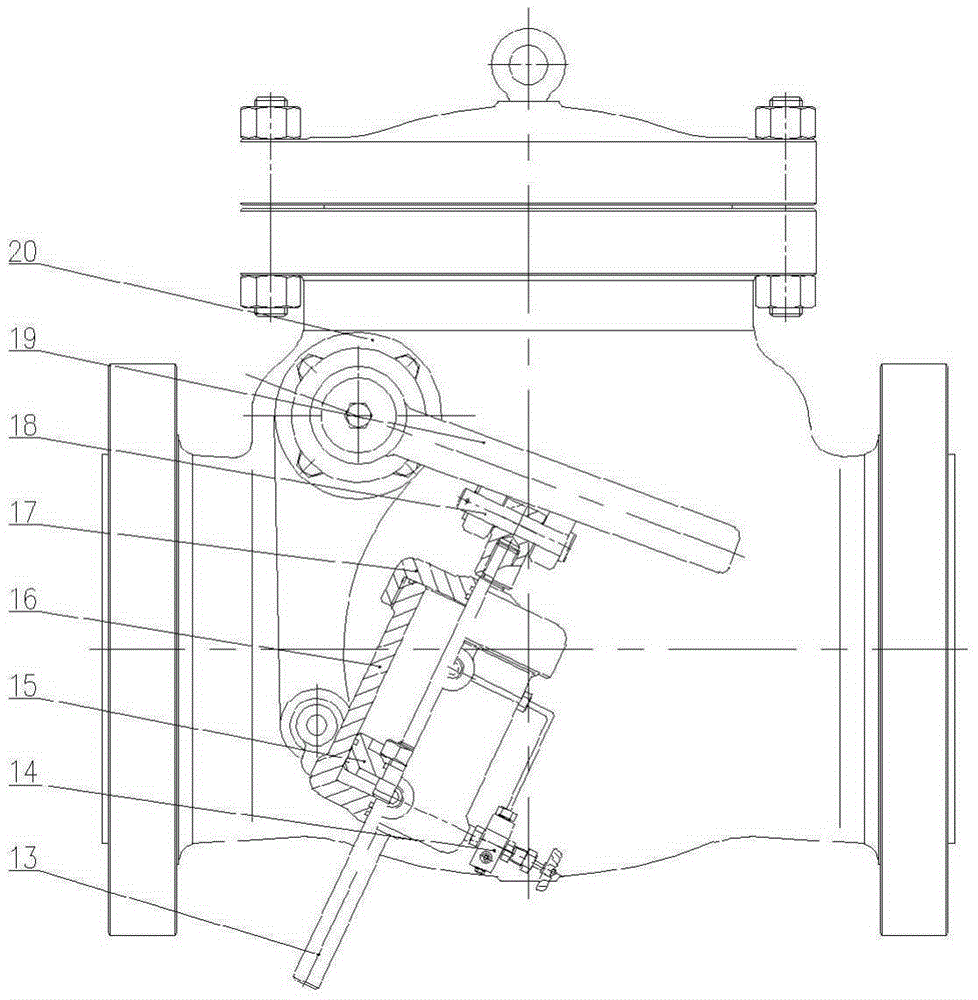
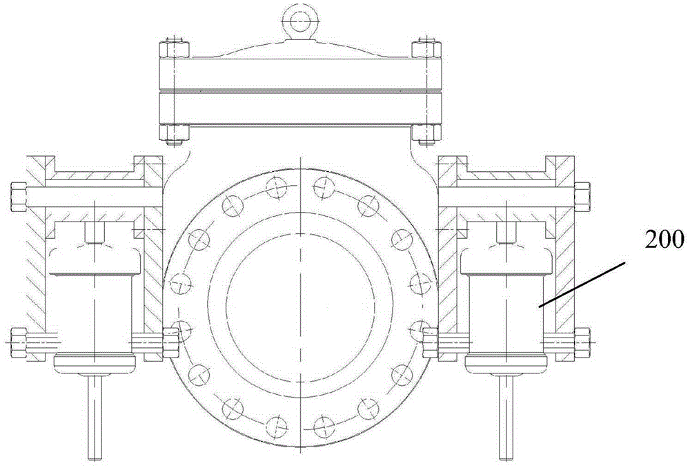
[0021] Such as figure 1 , figure 2 and image 3 As shown, the energy-saving non-resistance check valve of the present invention includes a valve body 1, a valve disc 2 and a valve cover 12, figure 1 The valve flap 2 in the dotted line position in represents its fully open position. The valve body 1 includes a medium inlet, a medium outlet and a valve chamber. The axial direction of the medium inlet coincides with the axial direction of the medium outlet. The valve chamber is located between the medium inlet and the medium outlet. The diameter of the valve chamber is larger than that of the medium inlet. , the bonnet 12 is in sealing connection with the valve body 1, the axial direction of the bonnet 12 is perpendicular to the axial direction of the medium inlet, the valve disc 2 is arranged in the valve cavity, wherein, a valve seat is arranged in the valve body 1, and the valve seat is located in the medium Between the inlet and the valve cavity, the axial direction of th...
Embodiment 2
[0031]The rocker 3 is connected with the valve flap 2 by bolts.
[0032] The working principle of the above embodiment is: the medium in the pipeline flows into the medium inlet of the valve body 1, the valve cavity is filled with medium, the medium pushes the valve disc 2 to swing, the valve disc 2 drives the valve stem 4 to rotate, and the valve stem 4 drives the rocker arm 19 rotates, the rocker arm 19 pulls the auxiliary valve rod 13 in the hydraulic slow closing device 200 to move upward, the auxiliary valve rod 13 drives the piston 15 to move, and the piston 15 pushes the hydraulic oil in the upper chamber of the hydraulic cylinder to flow into the lower chamber through the needle valve 14, so that The valve opens slowly. When the valve clack 2 is swung to a position parallel to the axial direction of the medium inlet, the valve clack 2 is located in the upturned chamber of the valve clack, and a flow channel with a full diameter is obtained between the medium inlet and ...
PUM
 Abstract
Description
Claims
Application Information
 - R&D
- Intellectual Property
- Life Sciences
- Materials
- Tech Scout
- Unparalleled Data Quality
- Higher Quality Content
- 60% Fewer Hallucinations
Browse by: Latest US Patents, China's latest patents, Technical Efficacy Thesaurus, Application Domain, Technology Topic, Popular Technical Reports.
© 2025 PatSnap. All rights reserved.Legal|Privacy policy|Modern Slavery Act Transparency Statement|Sitemap|About US| Contact US: help@patsnap.com


