Uniform light lens and LED light source module with same

A technology of LED light source and uniform light lens, applied in the direction of light source, point light source, semiconductor device of light-emitting element, etc., can solve the problems of narrowing the spot radius, unable to meet the design requirements of ultra-thin direct type backlight, etc. The effect of uniform distribution of illumination and convenient processing

Inactive Publication Date: 2014-07-16
FOSHAN INST SUN YAT SEN UNIV +1
View PDF6 Cites 8 Cited by
  • Summary
  • Abstract
  • Description
  • Claims
  • Application Information

AI Technical Summary

Problems solved by technology

However, if the light mixing distance of the fuselage is reduced to 15mm, the spot radius will be nearly doubled, and the number of light sources required to achieve the same level of uniformity will increase by 3 times, which cannot meet the design requirements of ultra-thin direct backlight

Method used


Image

  • Uniform light lens and LED light source module with same
  • Uniform light lens and LED light source module with same
  • Uniform light lens and LED light source module with same

Examples


Embodiment 1

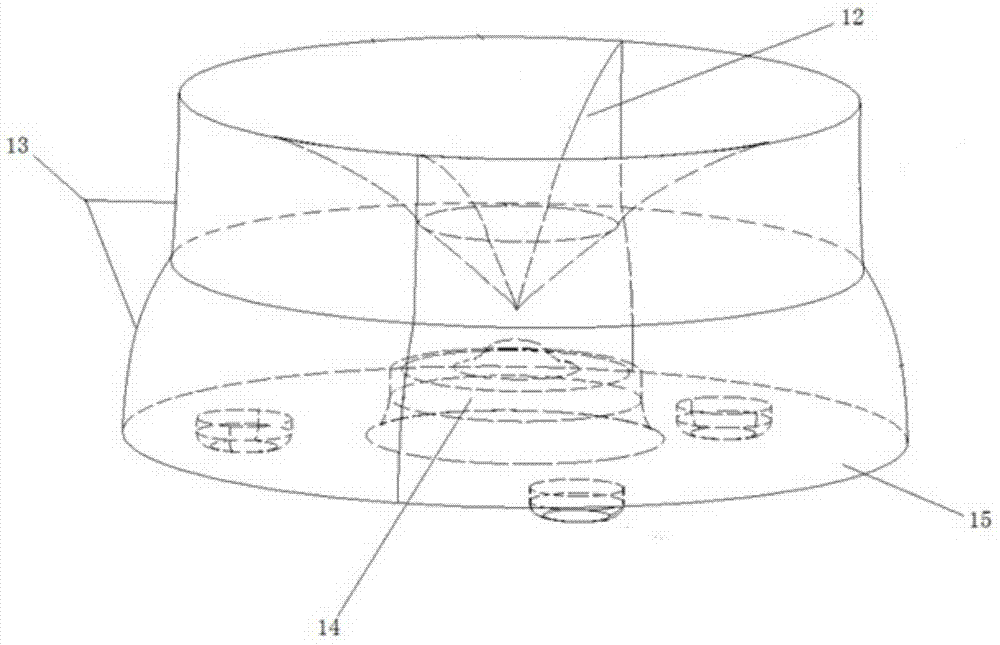
[0045] see figure 1 —3. A uniform light lens, the uniform light lens is a body of revolution, including a top exit surface 12, a side exit surface 13, an incident surface 14 and a bottom plane 15, the top exit surface 12 and the incident surface 14 are both along the A concave structure symmetrical to the axis of rotational symmetry 21 of the uniform light lens; on the section of the axis of rotational symmetry 21,

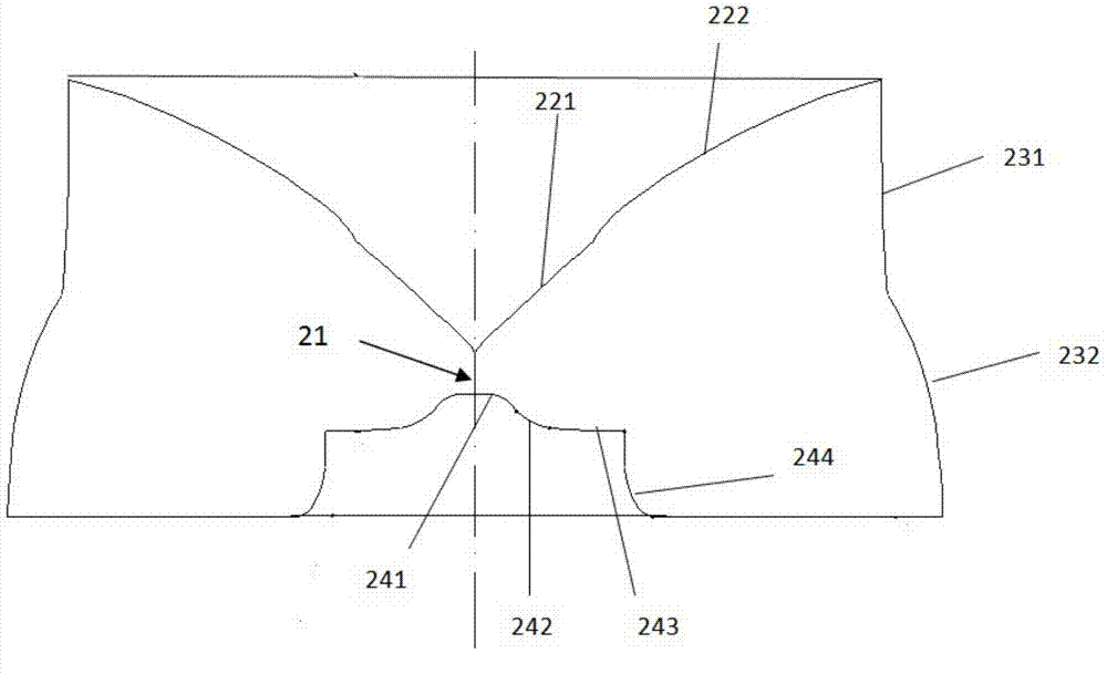
[0046] The top exit surface 12 includes an extension curve 221 and a parabola 222;

[0047] The side exit surface 13 includes a straight line segment 231 and an arc segment 232;

[0048] The incident surface 14 includes a top arc curve 241 , a first trapezoidal curve 242 , a second trapezoidal curve 243 and a lateral curve 244 connected in sequence.

[0049] In order to describe the structure of the uniform light lens more intuitively, from the cross-section, "lines" are used to describe the top exit surface, side exit surface, and incident surface; the "lines"...

Embodiment 2

[0062] see Figure 4 —5. The difference between the second embodiment and the first embodiment is that the bottom plane 15 is a frosted surface.

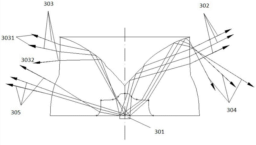
[0063] It is worth noting that in the whole design, no light directly reaches the position closest to the axis without passing through the surrounding reflective paper. This is because when the light mixing distance is extremely small, the central illuminance value should be reduced to less than 10% of the original state , bright spots may appear in any form of direct incidence. In this design, even if the original design does not directly illuminate the center, due to processing errors and light source luminous properties deviating from the design value, it is very likely that the center illuminance will be significantly higher than the surrounding area to form bright spots.

[0064] After research, it is found that the light at the position close to the edge on the lateral curve 244 has the smallest downward angle after refracti...

Embodiment 3

[0067] see Image 6 —7. The difference between the third embodiment and the first embodiment lies in that: the upper end area 502 of the straight section 231 of the side emitting surface 13 is a frosted surface, and the height of the frosted surface is≦0.5mm.

[0068] see Image 6 , due to processing errors and light source luminous properties deviating from the design value, the light 501 emitted from the LED light source 301 is incident at a position close to the edge of the second trapezoidal curve 243, reflected by the parabola 222, and then the straight line of the side exit surface 13 Segment 231 exits; since the angle at which the light 501 exits downward and reaches the reflective paper is very small, the problem of increased brightness at a position closer to the center is likely to occur after being reflected by the reflective paper. After research, it is found that this part of light 501 is concentrated on the upper end region 502 of the parabola 222 of the top ex...


PUM


Abstract

The invention discloses a uniform light lens which is a rotator and comprises a top emergent plane, side emergent planes, an incident plane and a bottom plane. The top emergent plane and the incident plane are of concave structures which are symmetrical along a rotational symmetry axis of the uniform light lens; the top emergent plane comprises an extension curve and a parabola on the section of the rotational symmetry axis; the side emergent planes comprise straight line sections and arc sections; the incident plane comprises top arc-shaped curves, first trapezoidal curves, second trapezoidal curves and lateral curves which are sequentially connected with one another. The uniform light lens has the advantages that the uniform light lens is exquisite in structure, and a uniform illumination effect can be realized under the conditions of ultra-short light mixing distances and ultra-far light source distances.

Description

technical field [0001] The invention relates to the field of optical design, in particular to a homogenizing lens and an LED light source module comprising the homogenizing lens. Background technique [0002] Due to its energy saving, wide color gamut, long lifespan, and fast adjustment speed, LEDs have gradually shown great advantages over traditional compact fluorescent light sources. Among the mainstream technical routes of LED backlighting, there are two mainstream technical routes of side-in and direct-lit. Compared with the side-in type (LED installed on the side of the display area), the core advantages of the direct-type technology (LED placed at the bottom of the display) include: large heat dissipation area of ​​the light source, easy to dissipate heat, and high reliability; easy to control local area brightness, contrast and The dynamic characteristics are better; the light loss of the direct light path is less; the light guide plate is omitted, and the cost of t...

Claims


Application Information

Patent Timeline
Patent Type & Authority Applications(China)
IPC IPC(8): F21V5/04F21Y101/02F21Y115/10
Inventor 罗滔王钢
Owner FOSHAN INST SUN YAT SEN UNIV
Why Eureka
Try Eureka