Fixture system for creep test

A fixture system and creep test technology, which is applied in the field of creep test fixture systems, can solve problems such as damaged equipment, threats to the personal safety of operators, and experiments that cannot be carried out, and achieve lower requirements, strong practicability, and reduced tensile strength Effect

Active Publication Date: 2014-07-16
CENT SOUTH UNIV
View PDF8 Cites 5 Cited by
  • Summary
  • Abstract
  • Description
  • Claims
  • Application Information

AI Technical Summary

Problems solved by technology

When this equipment is used for electrical pulse creep experiments, the pulse current is introduced to the sample through the output end of the pulse power supply. Since the sample, extension rod, and fixture system are all made of conductive materials, the current will inevitably be introduced into the creep testing machine to damage it. equipment and pose a threat to the personal safety of the operator, making it impossible to carry out the experiment

Method used


Image

  • Fixture system for creep test
  • Fixture system for creep test
  • Fixture system for creep test

Examples


Embodiment 1

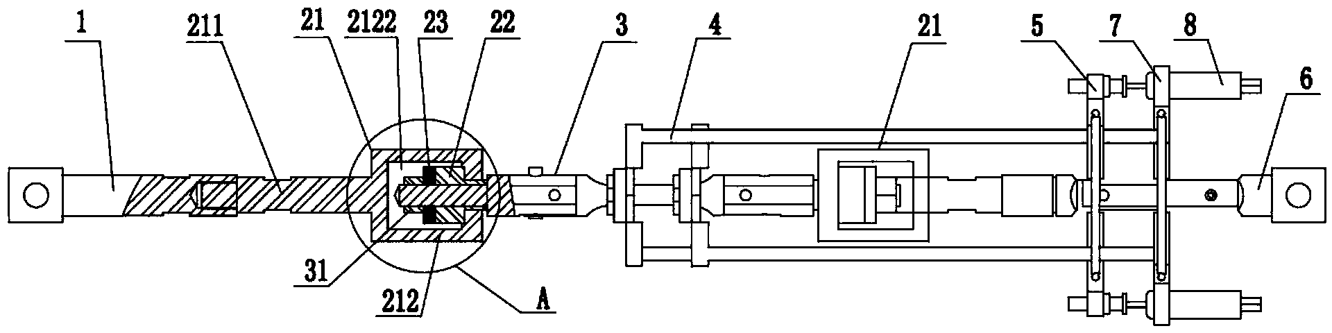
[0042] A fixture system for creep testing, see figure 1 , including an upper stretching rod 1 , a first connecting part, a second connecting part, a plate sample joint 3 , an extending rod 4 , an adjusting seat 5 and a lower stretching rod 6 .

[0043] The first connecting part includes a shoulder joint 21, a convex block 22 and a first gasket 23, and the overall structure is simplified.

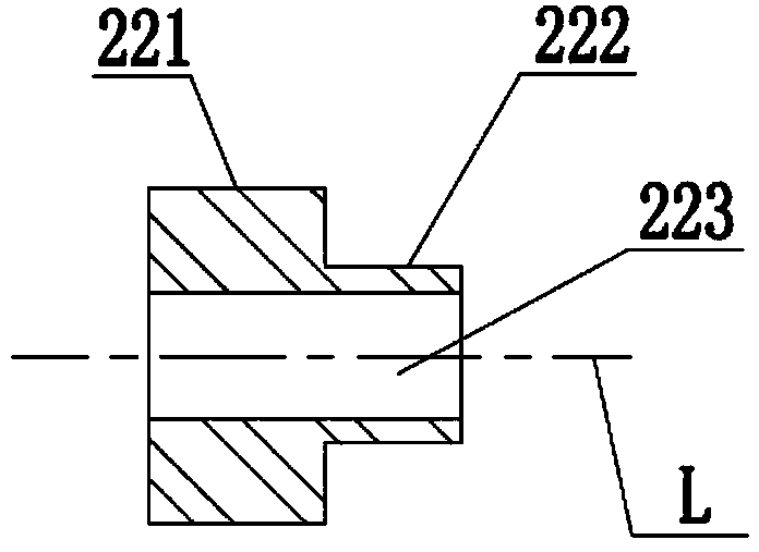
[0044] The convex block 22 includes a first end 221, a second end 222 and a first through hole 223, see figure 2 , on a plane perpendicular to the axis L thereof, the cross section of the first end 221 is larger than the cross section of the second end 222 , and the first through hole 223 is arranged along the axis L direction thereof.

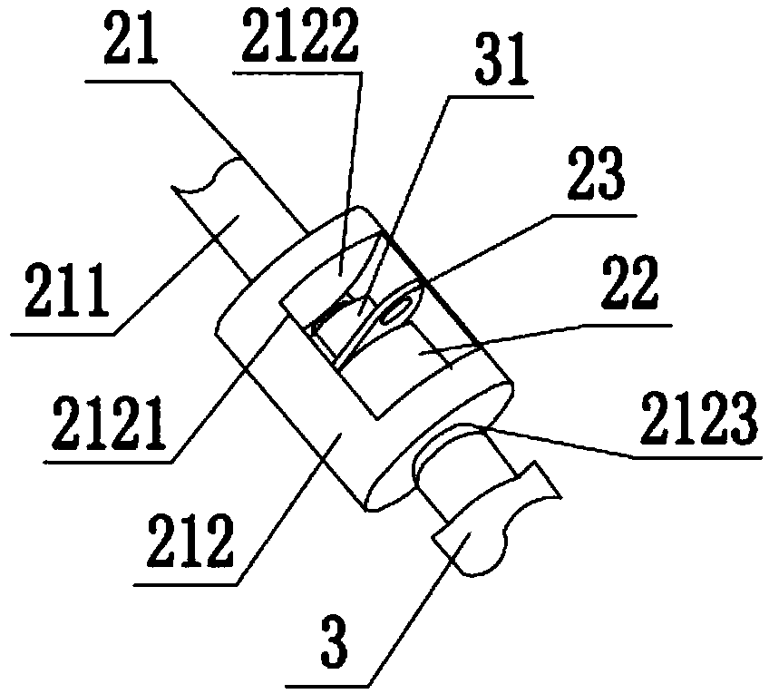
[0045] The shoulder joint 21 includes a connecting rod 211 and a frame body 212, see image 3 , the frame body 212 includes a cavity 2122 with an opening 2121, the front end of the connecting rod 211 is connected to the end of the upper stretch rod 1, and...

Embodiment 2

[0059] A clamp system for a creep test. Compared with Example 1, only the structures of the first connecting part and the second connecting part are different, and the first connecting part includes a first stopper 201, a second Stopper 202, second gasket 203, stretching block 204 and fixing part 205, see Image 6 as well as Figure 7 , the overall structure is simplified.

[0060] The first stopper 201, the second stopper 202, the second gasket 203 and the stretching block 204 are fixed by the fixing part 205, and the fixing part 205 adopts a combination of bolts and nuts adapted to each other, and is installed Convenience.

[0061] The first stopper 201 is arranged on the end surface of the end of the upper tensile rod 1 perpendicular to the axis of the upper stretching rod 1, and a third through hole is provided on it; the second stopper 202 is perpendicular to the plate sample The axis of the joint 3 is arranged on the end surface of its front end, and a fourth through ...


PUM

PropertyMeasurementUnit
thicknessaaaaaaaaaa

Abstract

The invention provides a fixture system for a creep test. The fixture system comprises an upper tensile rod, a plate sample joint, an extending rod, and a lower tensile rod, wherein a first connecting part is arranged between the upper tensile rod and the plate sample joint; a second connecting part is arranged between the plate sample joint and the lower tensile rod; the plate sample joint is coaxially connected with the extending rod; the structure of the second connecting part is the same as that of the first connecting part; the first connecting part is formed by combining a shoulder joint, a convex block and a first gasket or is formed by combining a first stopper, a second stopper, a second gasket, a tensile block and a fixing part. According to the design of the first connecting part and the second connecting part, a whole insulating material part is stressed with pressure instead of tension before, and thus the requirement on the tensile strength of the insulating material in the system is lowered. Moreover, the tensile block and the like are made of insulating materials, and the overall equipment is uncharged after pulse current is introduced, so that the safety performance of the equipment in the using process is improved, and a creep effect is good.

Description

technical field [0001] The invention relates to the field of material creep testing devices, in particular to a clamp system for creep testing. Background technique [0002] Creep age forming technology is more and more widely used in the aerospace field to meet the needs of large integral panel forming. Creep aging forming technology integrates the forming-based manufacturing environment and the forming-based heat treatment environment in time and space, and uses the creep and stress relaxation characteristics of materials to make the elastic pre-strain of the component to be formed partly after a certain period of time. It is a forming technology that converts into plastic strain to realize the forming and forming of parts at the same time. The disadvantages of creep aging forming are long cycle and high energy consumption. At the same time, high-end equipment manufacturing industries such as aerospace have higher and higher requirements on the processing and service perf...

Claims


Application Information

Patent Timeline
Patent Type & Authority Applications(China)
IPC IPC(8): G01N3/04
Inventor 湛利华张姣焦东军黄明辉贾树峰
Owner CENT SOUTH UNIV
Why Eureka
Try Eureka