A production method of continuous casting and rolling composite metal strip

A composite metal, continuous casting and rolling technology, applied in the direction of metal rolling, metal rolling, rolling mill control devices, etc., can solve the problems of insufficient bonding force between metal lithium and metal copper, waste of materials, thick thickness, etc., and achieve reduction Requirements for tensile strength, improvement of bonding strength, and the effect of high fluidity

Active Publication Date: 2022-02-15
QINGDAO NINEX NEW ENERGY TECH CO LTD
View PDF11 Cites 0 Cited by
  • Summary
  • Abstract
  • Description
  • Claims
  • Application Information

AI Technical Summary

Problems solved by technology

[0007] 1) It is difficult to prepare a lithium strip with a thickness of 2-20um on the surface of copper foil, that is, the thickness of metal lithium is relatively thick, which wastes materials;
[0008] 2) In the prepared negative electrode metal composite material, the binding force of metal lithium and metal copper is often not strong enough, and it is easy to fall off

Method used


Image

  • A production method of continuous casting and rolling composite metal strip
  • A production method of continuous casting and rolling composite metal strip
  • A production method of continuous casting and rolling composite metal strip

Examples


Embodiment 1

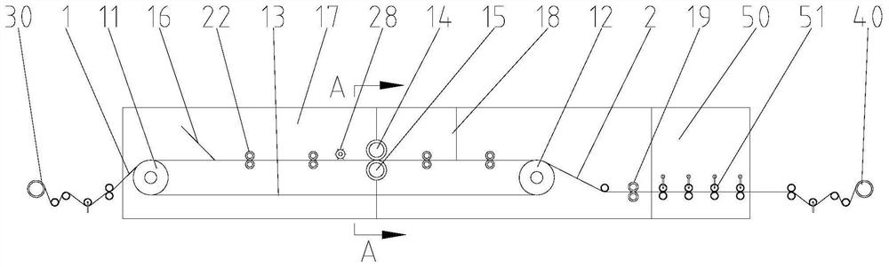
[0058] Such as figure 1 Shown is a schematic structural view of a continuous casting and rolling clad metal strip production line with the first structure applicable to the production method of continuous casting and rolling clad metal strip in Example 1 of the present invention. The continuous casting and rolling clad metal strip production line includes:

[0059] The transmission belt mechanism, the transmission belt mechanism includes a first transmission roller 11 and a second transmission roller 12 located at both ends, and a transmission belt 13 is set between the first transmission roller 11 and the second transmission roller 12;

[0060] The unwinding mechanism 30 is used to unwind the strip 1 that moves synchronously with the transmission belt 13;

[0061] Winding mechanism 40, used for winding the composite metal strip 2 obtained;

[0062] The transmission belt mechanism is provided with a control roller group for controlling the thickness of the metal material lay...

Embodiment 2

[0086] Such as Figure 11 Shown is a schematic structural view of a continuous casting and rolling composite metal strip production line with the first structure applicable to the production method of continuous casting and rolling composite metal strip of the present invention. The production line of the continuous casting and rolling composite metal strip of the present embodiment comprises:

[0087] The transmission belt mechanism, the transmission belt mechanism includes a first transmission roller 11 and a second transmission roller 12 located at both ends, and a transmission belt 13 is set between the first transmission roller 11 and the second transmission roller 12;

[0088] The unwinding mechanism 30 is used to unwind the strip 1 that moves synchronously with the transmission belt 13;

[0089] Winding mechanism 40, used for winding the composite metal strip 2 obtained;

[0090] The transmission belt mechanism is provided with a control roller group for controlling the...


PUM

PropertyMeasurementUnit
densityaaaaaaaaaa

Abstract

The invention discloses a production method of continuous casting and rolling composite metal strip. The strip is uncoiled and the strip is moved synchronously with the transmission belt. Liquid metal is added to the feeding side of the control roller group. The high temperature zone on the material side keeps the liquid metal liquid and fluid, the thickness of the liquid metal is controlled by the control roller group, and the liquid metal located on the strip is cooled and shaped into a composite on the belt by the cooling zone set on the discharge side of the control roller group. The metal material layer on the material is obtained to obtain a composite metal belt. The production method of the continuous casting and rolling composite metal strip of the present invention can precisely control the thickness of the metal material layer, that is, the thickness can be thinner to meet the use requirements of the energy storage electrode, and the bonding force is also better.

Description

technical field [0001] The invention relates to a production method of a metal strip, in particular to a production method of a continuous casting and rolling composite metal strip. Background technique [0002] The negative electrode of the lithium-ion battery is formed by mixing the negative electrode active material carbon material or non-carbon material, binder and additives, and the paste is evenly applied on both sides of the copper foil, dried and rolled. Whether lithium-ion batteries can be successfully manufactured depends on whether anode materials that can reversibly extract / intercalate lithium ions can be prepared. Generally speaking, the selection of a good anode material should follow the following principles: high specific energy; low electrode potential relative to lithium electrodes; good reversibility of charge and discharge reactions; good compatibility with electrolyte and binder; small specific surface area (<10m 2 / g), high true density (>2.0g / c...

Claims


Application Information

Patent Timeline
Patent Type & Authority Patents(China)
IPC IPC(8): B21B1/46B21B37/16B21B45/02B21B15/00
CPCB21B1/463B21B37/165B21B45/0203B21B15/00B21B2015/0064B21B2015/0057
Inventor 辛民昌李长明吴超辛程勋
Owner QINGDAO NINEX NEW ENERGY TECH CO LTD
Why Eureka
Try Eureka