Electronic paper display device

A display device, electronic paper technology, applied in the direction of instruments, optical components, optics, etc., can solve the problems of uneven color rendering, bright color, unstable dyeing of charged particles, etc., and achieve high practicability and generalizability, pure color Effect

Active Publication Date: 2014-07-16
BOE TECH GRP CO LTD +1
View PDF5 Cites 24 Cited by
  • Summary
  • Abstract
  • Description
  • Claims
  • Application Information

AI Technical Summary

Problems solved by technology

Although the above-mentioned technical scheme can realize the display of color patterns, it has the shortcomings of unstable dyeing of charged particles b

Method used


Image

  • Electronic paper display device
  • Electronic paper display device
  • Electronic paper display device

Examples


Embodiment approach

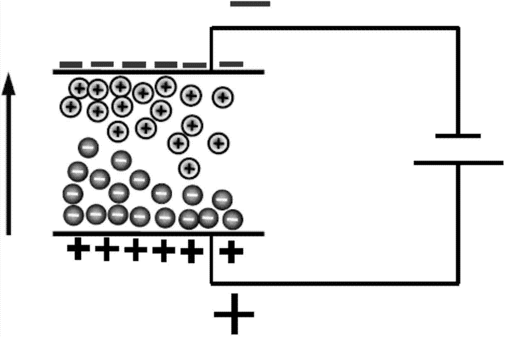
[0047] This solution includes but is not limited to the following embodiments: (1) The charged particles in the microcapsules of the present invention are composed of positively charged white particles and negatively charged black particles coated with a quantum dot layer, wherein the quantum dots The quantum dots in the dot layer are not charged. In this solution, the particle size of the quantum dots can be selected from one of the quantum dots used to display red, green and blue (18-20nm, 12-14nm and 6-8nm). When it is necessary to display black, control the voltage of the upper electrode to be greater than the voltage of the lower electrode, then it is a black picture from above. When wanting to display color patterns, control the voltage of the upper electrode to be lower than the voltage of the lower electrode, and at this time, the positively charged electron points move upward to the upper electrode. When external light is incident, the quantum dots are excited to emi...

Embodiment 1

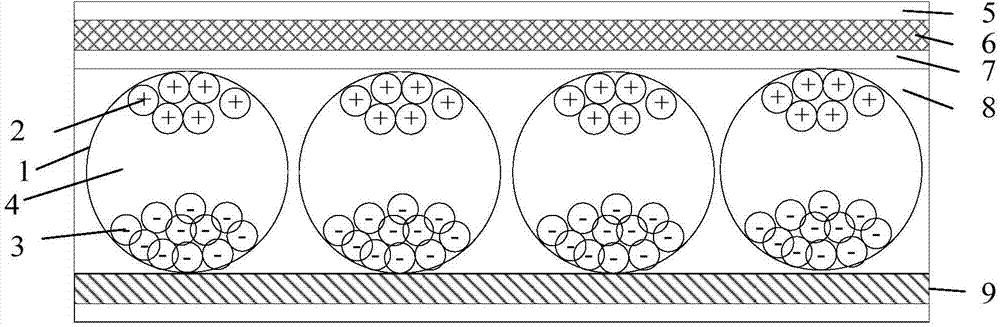
[0065] Such as figure 2 The film layer structure of the electrophoretic display (EPD) shown: from top to bottom, it includes protective film 5, organic plastic 6, ITO7, adhesive layer 8; adhesive layer 9 and pixel electrodes (not marked in the figure), in Microcapsules 1 are arranged in the adhesive layer 8 (between the two layers of electrodes).

[0066] Such as Figure 4 As shown, in this embodiment, the microcapsule 1 includes positively charged white particles 2 and negatively charged black particles 3, wherein the positively charged white particles 2 are coated with blue quantum dots 13. point layer.

[0067] When it is necessary to display black, control the voltage of the upper electrode to be greater than the voltage of the lower electrode, then it is a black picture from above. When wanting to display a blue pattern, control the voltage of the upper electrode to be lower than the voltage of the lower electrode, and at this time, the positively charged white partic...

Embodiment 2

[0070] Compared with embodiment 1, the difference is only in:

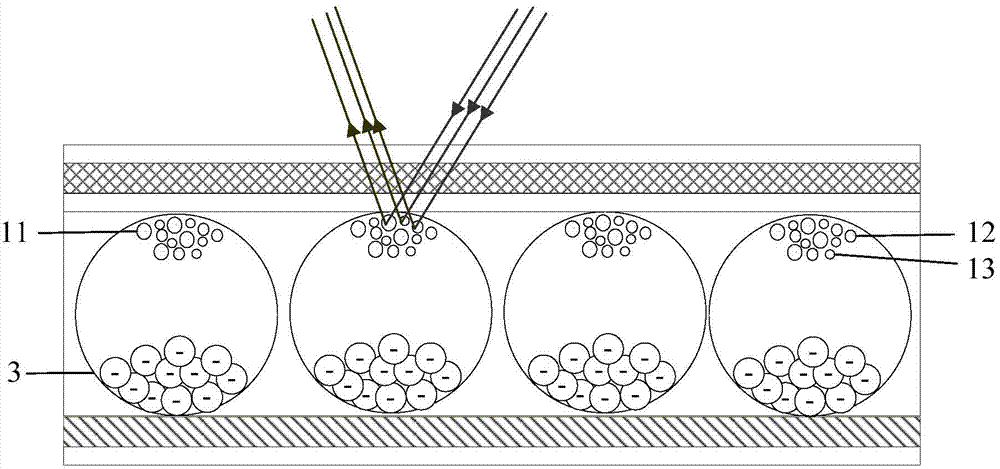
[0071] Such as Figure 5 As shown, in this embodiment, the microcapsule 1 includes positively charged white particles 2 and negatively charged black particles 3, wherein the negatively charged black particles 3 are coated with quantum dots composed of blue quantum dots 13 Floor.

[0072] When it is necessary to display blue, the voltage of the upper electrode is controlled to be greater than the voltage of the lower electrode, and when external light is incident, the quantum dots are excited to emit blue light to complete the blue display. When wanting to display a white pattern, the voltage of the upper electrode is controlled to be lower than the voltage of the lower electrode. At this time, the positively charged white particles 2 move upward to the upper electrode to complete white display.

[0073] In this embodiment, when the quantum dot layers are all made of 18-20nm quantum dots, this solution can realiz...


PUM

PropertyMeasurementUnit
Particle sizeaaaaaaaaaa

Abstract

The invention relates to an electronic paper display device. The electronic paper display device comprises an upper substrate with a first electrode layer formed thereon, a lower substrate with a second electrode layer formed thereon and an electronic ink layer arranged between the first electrode layer and the second electrode layer, microcapsules are distributed in the electronic ink layer, and at least one kind of quantum dots capable of displaying a kind of color are encapsulated in each microcapsule. Quantum dot display has various functions. If multiple excitation and light emission can be borne, long-lasting stability guarantees application effect. Besides, the biggest advantage of the quantum dots is rich color. Two-color display of electronic paper products within a broad color range can be realized through the quantum dots, and the electronic paper display device is purer in color and clearer and has higher practicality and generalizability.

Description

technical field [0001] The invention relates to a display device, in particular to an electronic display device capable of displaying multiple colors. Background technique [0002] Traditional liquid crystal display (LCD) equipment is limited to structural limitations so that its thickness cannot be too thin (if the thickness of the two layers of glass of the LCD display is 0.7mm, and the thickness of the two substrates is 0.5mm thick, then the LCD display The thickness of the screen will not be less than 2mm), and the weight cannot be too light. The hardware structure of the electronic ink display device is quite simple, its thickness can be about 1mm, and the thickness of the display screen is less than half of that of the LCD, and the weight of the electronic ink display device is also quite light, but the structure is stronger and more durable than the ordinary LCD . In addition, electronic ink has a wide range of applications. It can be used not only on glass surfaces...

Claims


Application Information

Patent Timeline
IPC IPC(8): G02F1/167G02F1/16757G02F1/1685
CPCG02F1/167Y10S977/774Y10S977/952B82Y20/00G02F2001/1678Y10S977/779Y10S977/932Y10S977/773G02F1/16757G02F1/1685G02F1/134336G02B5/0242G02B26/026G02F1/133348G02F2201/123G02F1/172
Inventor 曲连杰
Owner BOE TECH GRP CO LTD
Why Eureka
Try Eureka