
Method for optimizing gas-solid two-phase flow field and ammonia spraying of selective catalytic reduction denitration device

An optimization method and selective technology, applied in chemical instruments and methods, separation methods, instruments, etc., can solve the problems of high ammonia escape rate, catalyst wear and fouling, low denitration efficiency, etc., to improve denitration efficiency and prolong service life. , Reduce the effect of catalyst fouling

Active Publication Date: 2014-07-16
SOUTHEAST UNIV
View PDF3 Cites 25 Cited by
  • Summary
  • Abstract
  • Description
  • Claims
  • Application Information

AI Technical Summary

Problems solved by technology

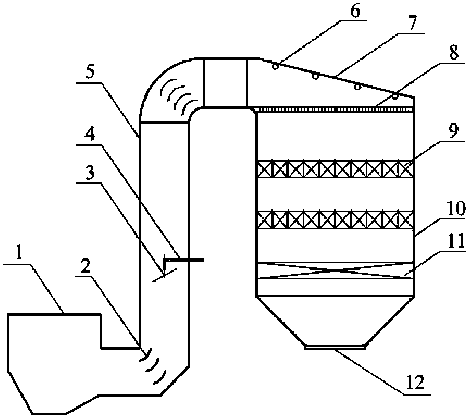
[0005] Purpose of the invention: In view of the above technical problems, the present invention provides a gas-solid two-phase flow field and ammonia injection control optimization method for a selective catalytic reduction denitrification device, which is used to solve the problem that the existing SCR denitrification device design optimization method is used to uniform inflow The optimization of inlet conditions and flow field uniformity does not take into account the influence of solid phase particle flow characteristics, and the uniform ammonia injection points at each ammonia injection point do not meet the actual conditions and parameters of the project. The denitrification efficiency of the SCR denitrification device is low under the premise that the ammonia escape rate meets the standard. , Under the premise that the denitrification efficiency reaches the standard, the ammonia escape rate is high, and the catalyst wears and ash is seriously deposited, etc.

Method used


Image

  • Method for optimizing gas-solid two-phase flow field and ammonia spraying of selective catalytic reduction denitration device

Examples


Embodiment Construction

[0019] The present invention provides a gas-solid two-phase flow field and ammonia injection control optimization method for an SCR denitrification device based on non-uniform inlet conditions. The steps of the method are as follows:

[0020] (1) According to the structure and size of the actual operating SCR denitrification device, use Gambit software to establish a three-dimensional physical model including the connecting flue and SCR reactor;

[0021] (2) Obtain the non-uniformity conditions at the inlet of the SCR denitrification device by means of experiments, numerical simulations or field tests (including the velocity distribution, temperature distribution, component concentration distribution of the flue gas on the inlet section and the concentration distribution of fly ash particles, particle size diameter distribution, etc.), and use this condition as the inlet boundary condition of the calculation model;

[0022] (3) Use Fluent software to simulate the gas-solid two...


PUM


Abstract

The invention provides a method for optimizing a gas-solid two-phase flow field and ammonia spraying of a selective catalytic reduction denitration device. The method includes the steps of obtaining the gas-solid two-phase flow characteristics of smoke and fly ash particles in an SCR denitration device by means of a non-uniform inlet boundary condition and by simulating the gas-solid two-phase flowing process of the SCR denitration device with the help of the Fluent software, processing the numerical calculation result through postprocessing software, analyzing the flow field uniformity problem existing in the SCR denitration device, optimizing the gas-solid two-phase flow field of the SCR denitration device by taking measures of changing the shape and the arrangement method of a diversion plate in a connection flue, changing the shape and the position of a rectification component on a ceiling of a reactor, changing the distances between rectification grating blades and the heights of the rectification grating blades and changing the structure of the SCR reactor, and other measures, calculating the NOx flux distribution of the area according to the smoke speed analysis and the concentration distribution of the ammonia spraying positions in the connection flue, and controlling the ammonia spraying amount matched with the NOx flux distribution in the area according to the optical ammonia nitrogen ratio.

Description

technical field [0001] The invention relates to a method suitable for the design and optimization of a selective catalytic reduction SCR denitrification device for power plant boilers, and belongs to the technical field of air pollutant control of coal-fired boilers. Background technique [0002] The Selective Catalytic Reduction (SCR) technology using ammonia as the reducing agent is currently the most effective technology for removing NOx from flue gas, and has been widely used in engineering at home and abroad. For the SCR denitrification device, its core is the catalyst. Under the action of the catalyst, the NOx in the flue gas and the NH of the reducing agent 3 Rapid reaction to generate N 2 and H 2 O. In order to fully exert the catalytic effect of the catalyst, it is necessary to ensure that the flow field distribution of the system is very uniform (including velocity distribution, ammonia nitrogen distribution, temperature distribution, etc.). In addition, in ord...

Claims


Application Information

Patent Timeline
IPC IPC(8): G06F17/50B01D53/90B01D53/56
Inventor 金保昇张勇陈天杰姚露
Owner SOUTHEAST UNIV
Learn More