Static synchronous compensation circuit and decoupling control method thereof

A static synchronous compensation and decoupling control technology, applied in reactive power adjustment/elimination/compensation, flexible AC transmission system, etc., can solve problems such as high cost and price increase, and achieve voltage stress reduction and total harmonic distortion reduction rate effect

Active Publication Date: 2014-07-16
西安西驰电气股份有限公司
View PDF4 Cites 8 Cited by
  • Summary
  • Abstract
  • Description
  • Claims
  • Application Information

AI Technical Summary

Problems solved by technology

Since STATCOM is a smart device of all-power electronic technology, its cost is relatively high at present, and its price increases exponentially with the increase of withstand voltage level of switching devices

Method used


Image

  • Static synchronous compensation circuit and decoupling control method thereof
  • Static synchronous compensation circuit and decoupling control method thereof
  • Static synchronous compensation circuit and decoupling control method thereof

Examples


Embodiment Construction

[0024] The present invention will be described in detail below in conjunction with the accompanying drawings and specific embodiments.

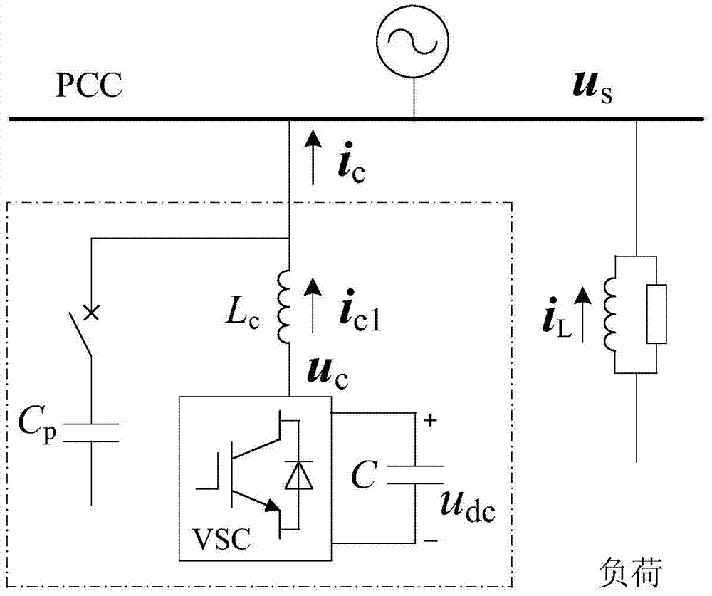
[0025] figure 1 It is a typical topology of traditional static synchronous compensation circuit, capacitor C p It is connected to the power distribution system in parallel with the static synchronous compensator (STATCOM), and the static synchronous compensator is connected in parallel with the DC capacitor C and the voltage source converter VSC, and then connected with the filter inductor L c And then connected in series. By adjusting the VSC inverter output voltage U c and grid side voltage U s The relative size of the dynamic continuous compensation of reactive power load changes. image 3 The line segment AB in represents the U of the static synchronous compensator c The relationship between its reactive power compensation current, the line segment BG represents C p The reactive power compensation current characteristics of , the li...


PUM


Abstract

The invention discloses a static synchronous compensation circuit. The static synchronous compensation circuit comprises a static synchronous compensator. The output end of the static synchronous compensator is connected with a capacitor Cc in series and then connected into a power distribution system. The invention further discloses a decoupling control method based on the static synchronous compensation circuit. The decoupling control method based on the static synchronous compensation circuit comprises the steps that firstly, the alternating-current voltage us on a net-side PCC and the alternating-current voltage ucs on the capacitor Cc are detected through a voltage inductor, and a reactive compensation current ic is detected through a current inductor; secondly, the voltage udc on a direct-current capacitor C is obtained through a direct-current voltage detection circuit; thirdly, a balance equation of voltage on the alternating-current side of a VSC and a relational expression between the voltage and the current on the capacitor Cc are listed; fourthly, double loop control of an outer voltage loop and an inner current loop is adopted by the static synchronous compensator. By the adoption of the static synchronous compensation circuit and the decoupling control method based on the static synchronous compensation circuit, the starting performance is remarkably improved, the voltage stress of a switching device is reduced obviously, and the total harmonic distortion of an output current of a compensation device is reduced.

Description

technical field [0001] The invention belongs to the technical field of power system reactive power compensation, and relates to a static synchronous compensation circuit, and also relates to a decoupling control method based on the static synchronous compensation circuit. Background technique [0002] In the user power distribution system, inductive equipment such as power transformers, AC motors and AC reactors are widely used, which absorb a large amount of reactive power from the grid, increase the line current, and generate additional additional power loss in the transmission line; Power quality problems such as voltage fluctuations caused by the start of some loads (such as AC motors) will have a serious impact on a large number of sensitive electrical equipment. Rapid dynamic compensation of reactive power in the power system can realize dynamic correction of load power factor, reduce line loss, improve static and dynamic stability of the power system, damp power oscil...

Claims


Application Information

Patent Timeline
Patent Type & Authority Applications(China)
IPC IPC(8): H02J3/18
CPCY02E40/10
Inventor 同向前张新闻
Owner 西安西驰电气股份有限公司
Why Eureka
Try Eureka