
Clamp for copper wire welding

A copper wire and fixture technology, applied in welding equipment, auxiliary welding equipment, welding/cutting auxiliary equipment, etc., can solve problems such as irregular welding joints, affecting the safe use of transformers, affecting welding quality and appearance, etc., to achieve clamping effect Excellent, simple structure, intuitive and reliable effect

Active Publication Date: 2014-07-23
南京金焊焊接实业有限公司
View PDF15 Cites 4 Cited by
  • Summary
  • Abstract
  • Description
  • Claims
  • Application Information

AI Technical Summary

Problems solved by technology

[0003] Most of the existing copper wire welding is random and random joint welding, so that the welding joints appear irregular, which affects the welding quality and appearance, and in severe cases, it also affects the safe use of the transformer

Method used


Image

  • Clamp for copper wire welding
  • Clamp for copper wire welding
  • Clamp for copper wire welding

Examples


Embodiment Construction

[0020] Below in conjunction with accompanying drawing of description, the present invention will be further described.

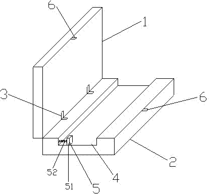
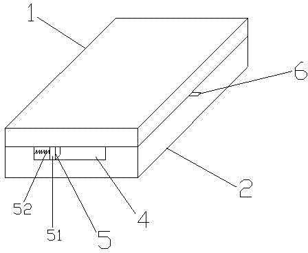
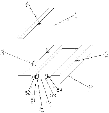
[0021] like figure 1 and figure 2 The first embodiment shown is a clamp for copper wire welding, which includes an upper clamping block 1 and a lower clamping block 2, which are fastened to each other and arranged in parallel, and are connected at the same end by a movable connector 3, and in addition In the middle part of the lower clamping block 2, there is a copper wire placement groove 4 communicating front and back, and the height of the copper wire placement groove 4 is the diameter of the copper wire; The block assembly 5 is composed of a block 51 and a spring 52 . A fastening part 6 is also provided at the other end of the upper clamping block 1 and the lower clamping block 2 opposite to the movable connecting part 3 . The movable connecting part 3 of the present invention is a hinge connecting part; the fastening part 6 is a buckle structure, wh...


PUM


Abstract

The invention discloses a clamp for copper wire welding. The clamp comprises an upper clamping block and a lower clamping block, wherein the upper clamping block and the lower clamping block are buckled to each other and arranged in parallel, one end of the upper clamping block and the corresponding end of the lower clamping block are connected through a movable connecting piece, a copper wire placement groove which is through in a front and rear mode is formed in the middle of the lower clamping block, the height of the copper wire placement groove is equal to the diameter of a copper wire, a stop dog assembly which horizontally move in a left and right mode is further arranged on the inner side edge of the copper wire placement groove, and the stop dog assembly is composed of a stop dog and a spring. The clamp further comprises a buckling part which is arranged at the other end, opposite to the movable connecting piece, of the upper clamping block and the other end, opposite to the movable connecting piece, of the lower clamping block. According to the clamp for copper wire welding, the process of placing the copper wire into the groove is visual, the phenomenon that the copper wire is bent in the hole penetration process is avoided, and the placement efficiency is improved; meanwhile, the copper wire bears stress in the perpendicular direction and the horizontal direction so that the copper wire can be arranged flat, it is ensured that copper wire joints are firm and flat, the requirement for arrangement of a plurality of copper wires can be met through width adjustment, and the clamp is simple in structure, convenient to use and high in practicability.

Description

technical field [0001] The invention relates to a fixture, in particular to a fixture for copper wire welding. Background technique [0002] With the rapid development of power technology and electronic equipment, the voltage level and capacity of transformers are constantly increasing, which often involves the welding of copper wires. [0003] Most of the existing copper wire welding is that the joints are randomly combined and welded, so that the welded joints appear irregular, which affects the welding quality and appearance, and in severe cases, also affects the safe use of the transformer. Contents of the invention [0004] The main purpose of the present invention is to overcome the deficiencies in the prior art and provide a copper wire welding jig, which is especially suitable for welding multi-strand copper wires. [0005] The technical problem to be solved by the present invention is to provide a simple structure, easy to use, low production cost, intuitive and ...

Claims


Application Information

Patent Timeline
Patent Type & Authority Applications(China)
IPC IPC(8): B23K37/04
CPCB23K37/0435B23K2101/32B23K2101/38
Inventor 任育文
Owner 南京金焊焊接实业有限公司
Learn More