
Electro-hydraulic valve for engine and working system thereof

A technology of engine and valve, applied in the direction of engine components, engine control, machine/engine, etc., can solve the problems of high manufacturing cost, large driving loss, complex structure, etc., and achieve the effect of improving power performance, reducing emissions, and reducing manufacturing cost

Inactive Publication Date: 2014-07-23
王欣亮 +1
View PDF5 Cites 5 Cited by
  • Summary
  • Abstract
  • Description
  • Claims
  • Application Information

AI Technical Summary

Problems solved by technology

[0018] The objective shortcoming of above-mentioned prior art is that structure is complicated, manufacturing cost is high, and driving loss is also big

Method used


Image

  • Electro-hydraulic valve for engine and working system thereof
  • Electro-hydraulic valve for engine and working system thereof
  • Electro-hydraulic valve for engine and working system thereof

Examples


Embodiment Construction

[0034] The present invention is described below in conjunction with accompanying drawing.

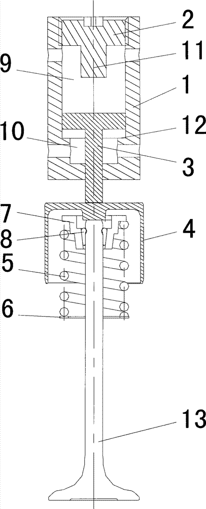
[0035] as attached figure 1Shown is a kind of electro-hydraulic valve for an engine according to the present invention, comprising an oil cylinder 1, a plunger 3, a tappet 4, a valve spring 5, and a valve 13; the top of the oil cylinder 1 is provided with an oil cylinder cover 2; the oil cylinder 1 is provided with No. 1 oil chamber 9 and No. 2 oil chamber 10 which communicate with each other; the inner diameter of No. 1 oil chamber 9 is larger than that of No. 2 oil chamber 10; the No. 1 oil chamber 9 is located in No. 2 oil above the cavity 10; the junction of the No. 1 oil cavity 9 and the No. 2 oil cavity 10 is formed with a step 12; the oil cylinder 1 is respectively provided with the No. Oil outlet hole of chamber (not marked), oil inlet hole of No. 2 oil chamber (not marked), oil outlet hole of No. 2 oil chamber (not marked); oil inlet hole of No. 1 oil chamber, No. 1 oil chambe...


PUM


Abstract

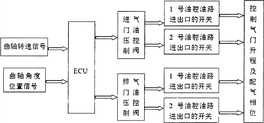
The invention discloses an electro-hydraulic valve for an engine and a working system thereof. The electro-hydraulic valve for the engine comprises an oil cylinder, a plunger and a valve body. An oil cylinder cover is arranged on the top of the oil cylinder, and a first oil cavity and a second oil cavity which are communicated with each other are formed in the oil cylinder. The plunger comprises a piston and a piston rod, wherein one end of the piston rod is perpendicularly arranged in the middle of the lower surface of the piston, the piston is arranged in the first oil cavity, and the other end of the piston rod penetrates through the second oil cavity, stretches out of the oil cylinder and can push the valve body to move vertically. According to the working system of the electro-hydraulic valve for the engine, an automobile computer controls opening or closing of an intake valve oil pressure control valve or an exhaust valve oil pressure control valve according to signals acquired by a crankshaft rotation speed signal sensor and a crankshaft angle and position signal sensor, and therefore the valve body in the electro-hydraulic valve for the engine can move to achieve intake or exhaust of the engine. By means of the electro-hydraulic valve for the engine and the working system thereof, the optimal intake or exhaust effect of the engine can be achieved.

Description

technical field [0001] The invention relates to an improvement of an engine valve, in particular to an engine electric hydraulic valve and its working system which can improve the best intake and exhaust effects of the engine. Background technique [0002] In the current mechanical manufacturing field, there are some reciprocating motions that need to be realized by camshafts, balance wheels or worms. For example, in the automotive engine manufacturing industry, the reciprocating motion of the valve has always been realized by the rotational motion of the camshaft. The valve train parts that drive the valve movement include camshaft, tappet, push rod, rocker arm, rocker shaft, rocker shaft seat and valve clearance adjustment screw, camshaft driven gear, transmission chain or toothed belt, transmission Chain guides, tensioners, half-moon keys, camshaft thrust plates, cam bearing caps and other components have complex structures, large layout space, high manufacturing costs, a...

Claims


Application Information

Patent Timeline
Patent Type & Authority Applications(China)
IPC IPC(8): F01L9/02F02D13/02F01L9/10
Inventor 王欣亮梁文
Owner 王欣亮
Learn More