Tunnel kiln

A tunnel kiln and kiln chamber technology, applied in the field of building materials, can solve problems such as increased production costs, large energy consumption, and sensitivity, and achieve the effects of reducing harmful components, reducing pollution, and reducing costs

Active Publication Date: 2014-07-23
FOSHAN DONGPENG CERAMIC +2
View PDF6 Cites 2 Cited by
  • Summary
  • Abstract
  • Description
  • Claims
  • Application Information

AI Technical Summary

Problems solved by technology

[0010] However, at present, the flash decoration of tiles needs to use lithographic flash powder, which is very rigid and uniform, and the labor intensity of workers is also high, and the material consumption is also high.
When ceramic tiles decorated with flash powder are calcined at high temperature in a kiln, the flash powder is very unstable and sensitive to the atmosphere of the kiln, causing some flash powder to be bright and some not bright, making production control difficult
As for the flash powder itself, because it contains rare metal elements (such as Ce) to flash, its price is relatively high, its manufacture is difficult, and its use and manufacture consumes a lot of resources.
And the existing flash powder is generally embossed flash, can not melt flash
[0011] In the process of kiln production, a lot of energy needs to be consumed, because most of the ceramic raw materials contain sulfur elements, such as pyrite (FeS 2 ), iron sulfate, calcium sulfate, sodium sulfate, etc., in the firing process, easily lead to the generation of sulfur dioxide, SO 2 Gas not only pollutes the environment and destroys ecology, but also directly affects the production quality of products and corrodes production equipment
The treatment of kiln exhaust gas leads to an increase in production costs. If it is not handled properly, it will easily cause serious environmental pollution

Method used


Image

  • Tunnel kiln
  • Tunnel kiln
  • Tunnel kiln

Examples


Embodiment 1

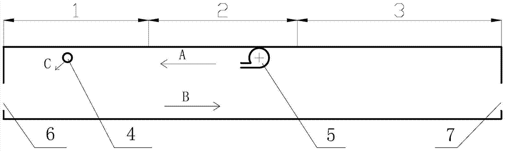
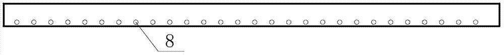
[0101] A roller kiln consists of a kiln chamber, combustion equipment (not shown in the drawings), ventilation equipment (not shown in the drawings), and conveying equipment (not shown in the drawings). The brick inlet 6 to the brick outlet 7 includes a heating section and a cooling section 3 in turn, and the heating section includes a preheating section 1 and a firing section 2 in turn, and the farther the heating section is from the brick inlet, the higher the temperature. High; a dehumidifying fan 5 is set in the firing section to discharge the kiln waste gas out of the kiln chamber; a straight pipe is installed above the tile transportation surface of the preheating section 1 as a cold air pipe 4, and the cold air pipe 4 is Set blowing holes 8, the blowing holes are evenly arranged on the cold air pipe, and the air outlet direction (C direction) of the blowing holes is obliquely downward to blow air, and is opposite to the conveying direction of the tiles (the air outlet di...

Embodiment 2

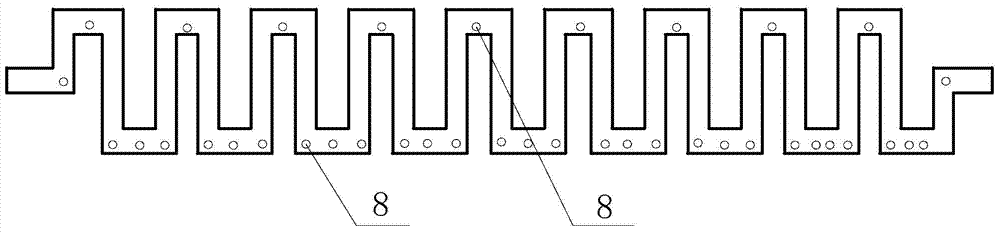
[0107] A roller kiln is composed of a kiln chamber, combustion equipment, ventilation equipment, and conveying equipment. The kiln chamber includes a heating section and a cooling section in turn from the brick inlet to the brick outlet. The heating section includes a preheating section in turn. Section and firing section, the farther the heating section is from the brick inlet, the higher the temperature; a dehumidifier is installed in the firing section to discharge the kiln waste gas from the kiln chamber; the ceramic tile transportation surface in the preheating section An S-shaped pipe is installed on the top of the cold air pipe as a cold air pipe, and blowing holes are arranged on the cold air pipe, and the blowing holes are evenly arranged on the cold air pipe. The direction is opposite (the air outlet direction of the blowing hole is at an angle of 60° to the horizontal), the aperture of the blowing hole is 3mm; and the cold air pipe can vibrate;

[0108] The cold air...

Embodiment 3

[0111] A roller kiln is composed of a kiln chamber, combustion equipment, ventilation equipment, and conveying equipment. The kiln chamber includes a heating section and a cooling section in turn from the brick inlet to the brick outlet. The heating section includes a preheating section in turn. Section and firing section, the farther the heating section is from the brick inlet, the higher the temperature; a dehumidifier is installed in the firing section to discharge the kiln waste gas from the kiln chamber; the ceramic tile transportation surface in the preheating section There are 3 straight pipes installed above as cold air pipes. Blowing holes are arranged on the cold air pipes. The blowing holes are evenly arranged on the cold air pipes. The same (the air outlet direction of the blowing hole is at an angle of 45° to the horizontal), the aperture of the blowing hole is 7mm; and the cold air pipe can vibrate;

[0112] The cold air pipe is installed at 480-550°C in the preh...


PUM

PropertyMeasurementUnit
pore sizeaaaaaaaaaa

Abstract

The invention relates to a tunnel kiln. The tunnel kiln is composed of a kiln chamber, a combustion device, a ventilation device and a conveying device. The kiln chamber sequentially comprises a heating section and a cooling section from a brick inlet and a brick outlet. The heating section sequentially comprises a preheating section and a sintering section. The further the heating section is away from the brick inlet, the higher the temperature is. A cold air pipe is installed above a ceramic tile conveying surface of the preheating section. Blow holes are formed in the cold air pipe. The air outlet direction of the blow holes is downward, and the cold air pipe can vibrate. According to the tunnel kiln, glistening glaze crystals are obtained through furnace transmutation of waste gas of the kiln, waste is turned into wealth, the problem that waste gas of the kiln pollutes the environment is solved, cost for treating the waste gas of the kiln is reduced, operation is simple and easy to control, and prepared glistening glazed ceramic tiles are stable in performance and unique in effect.

Description

[0001] This patent application is a divisional application, the application number of the original application is 201210555621.7, the application date is December 19, 2012, and the title of the invention is: "A method for preparing flashing glazed tiles" technical field [0002] The invention relates to a tunnel kiln and a method for preparing flashing glazed tiles, in particular to a tunnel kiln with a cold air duct in the preheating section, and a method for preparing flashing glazed tiles with the tunnel kiln, belonging to Building materials field. Background technique [0003] Ceramic tiles are plate-shaped or block-shaped ceramic products produced by clay and other inorganic non-metallic raw materials through molding and sintering processes. They are used to decorate and protect buildings, walls and floors of buildings. [0004] The method of firing ordinary clay ceramic products in a tunnel kiln can be divided into several processes: (1) remove residual moisture in the...

Claims


Application Information

Patent Timeline
Patent Type & Authority Applications(China)
IPC IPC(8): F27B9/02F27B9/30C04B41/89C04B41/86C04B33/13C04B33/34
Inventor 钟保民祁国亮
Owner FOSHAN DONGPENG CERAMIC
Why Eureka
Try Eureka