Generation Method of Spliced ​​Planar Spiral Inductor

A planar spiral and splicing technology, applied in the direction of inductors, circuits, electrical components, etc., can solve the problems that cannot fully meet the design needs, have no inductance model, single variety, etc., and achieve fast and effective generation methods, clear structures, and parameter settings. simple effect

Active Publication Date: 2016-08-17
CHINA ELECTRONIC TECH GRP CORP NO 38 RES INST
View PDF5 Cites 0 Cited by
  • Summary
  • Abstract
  • Description
  • Claims
  • Application Information

AI Technical Summary

Problems solved by technology

In the existing layout design, the inductance model is generally quadrilateral and octagonal, and based on the regular polygon structure, the variety is relatively single, which cannot fully meet the design needs; in addition, in the 3D electromagnetic simulation, there is often no inductance model, and the plane needs to be designed by itself Spiral inductor

Method used


Image

  • Generation Method of Spliced ​​Planar Spiral Inductor
  • Generation Method of Spliced ​​Planar Spiral Inductor
  • Generation Method of Spliced ​​Planar Spiral Inductor

Examples


Embodiment 1

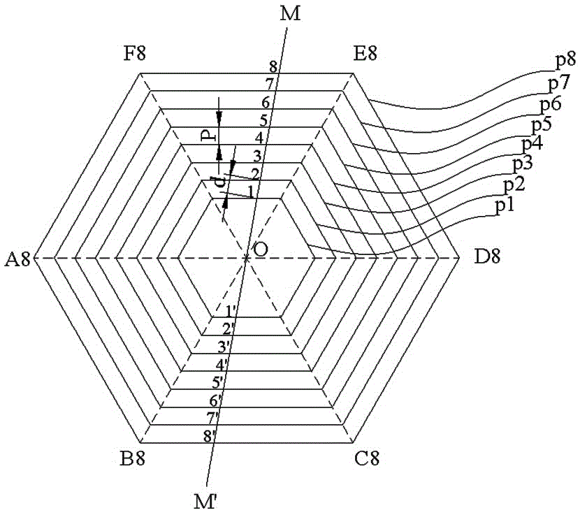
[0027] Such as figure 1 As shown, a group of concentric regular hexagons is generated, the center point is O, the sides of the regular hexagons are correspondingly parallel, and the distance between the corresponding sides of adjacent regular hexagons is a fixed value P. The regular hexagons are numbered as p1, p2, ... p8 from inside to outside. The vertices of p1 are A1, B1, C1, D1, E1, F1; the vertices of p2 are A2, B2, C2, D2, E2, F2; and so on, the vertices of p8 are A8, B8, C8, D8 , E8, F8.

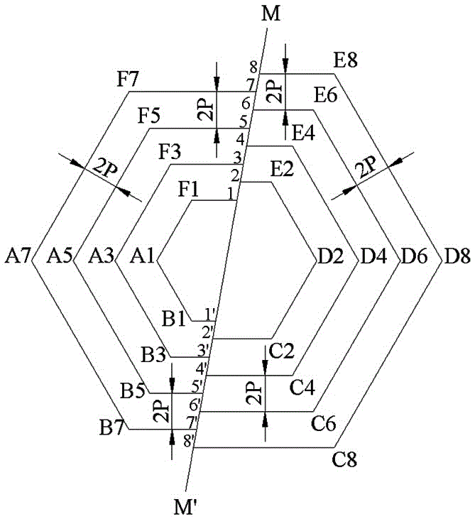
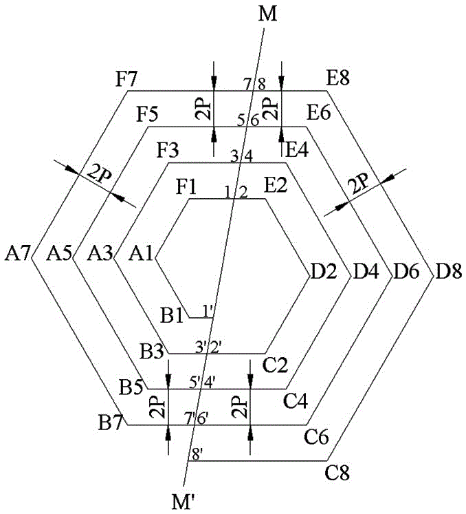
[0028] The straight line MM' intersects [E1, F1] at point 1, [E1, F1] refers to the line segment whose two end points are E1, F1, and so on, intersects [E2, F2] at point 2, ..., intersects [E8, F8] at point 8; straight line MM' intersects [B1, C1] at point 1', intersects [B2, C2] at point 2', ..., intersects [B8, C8] at point 8'. Due to the structural characteristics of regular hexagons, side [E1, F1] is parallel to side [B1, C1], side [E2, F2] is parallel to side [B2, C2], and so...

Embodiment 2

[0034] Such as Figure 5 As shown, a group of concentric regular pentagons is generated, the center point is O, the sides of the regular pentagons are correspondingly parallel, and the distance between the corresponding sides of adjacent regular pentagons is a fixed value P. The regular pentagons are numbered p1, p2, ... p8 from the inside to the outside. The vertices of p1 are A1, B1, C1, D1, E1; the vertices of p2 are A2, B2, C2, D2, E2; and so on, the vertices of p8 are A8, B8, C8, D8, E8.

[0035]Said set of concentric regular pentagons is symmetrical about the axis of symmetry NN'. Due to the regular pentagon structure, any two sides are not parallel to each other, so it is impossible to make a straight line intersect two sets of parallel sides as in the first embodiment. In this embodiment, the straight line MM' can be made perpendicular to the axis of symmetry NN'.

[0036] Line MM' intersects [D1, E1] at point 1, intersects [D2, E2] at point 2, ..., intersects [D8, ...

Embodiment 3

[0041] Such as Figure 8 As shown, the octagon p1 is first generated, and the vertices are A1, B1, C1, D1, E1, F1, G1, and H1 respectively. The interior angles of the octagon p1 are all 135°, and the octagon p1 is symmetrical about the straight line NN' and symmetrical about the straight line MM'. For other sizes see Figure 8 , the unit is μm.

[0042] Such as Figure 9 As shown, each side of p1 is equally spaced and extended to meet each other to form a group of similar polygons, and the equal space value is P=3μm. Line MM' vertically intersects [G1, F1] at point 1, perpendicularly intersects [G2, F2] at point 2, ..., perpendicularly intersects [G7, E7] at point 7; straight line MM' perpendicularly intersects [B1, C1] at point 1', perpendicular to [B2, C2] at point 2', ..., perpendicular to [B7, C7] at point 7'. It is easy to obtain that the line segment length d=P=3μm obtained by cutting the straight line M M' on the polygon group.

[0043] With reference to Example 1...


PUM


Abstract

The invention relates to a generation method of a spliced planar spiral inductor. The method comprises the following steps that a set of similar polygons are segmented through a segmentation straight line, the central points of the similar polygons coincide, and the distance P between any two adjacent polygons is equal to that between other two adjacent polygons; the similar polygons are numbered from inside to outside, segments of the polygons with the odd numbers on one side of the segmentation straight line are obtained, and segments of the polygons with the even numbers on the other side of the segmentation straight line are obtained; in the direction of the segmentation straight line, the segments of the polygons with the odd numbers on one side of the segmentation straight line and the segments of the polygons with the even numbers on the other side of the segmentation straight line are horizontally moved and spliced, wherein the horizontal moving distance is d, and a planar spiral line with the coil separation distance being 2P is generated; the planar spiral line serves as the central line, the segments are respectively perpendicularly and horizontally moved towards two sides by the distance of W / 2, and the horizontally-moved segments intersect to generate the planar spiral inductor with the line width being W and the coil separation distance being S. According to the generation method of the spliced planar spiral inductor, parameters are easy to set, the structure is clear, the generation method is rapid to implement and effective, and the planar spiral inductor with the same coil separation distance can be generated.

Description

technical field [0001] The invention relates to the technical field of integrated circuit device manufacturing, in particular to a method for generating spliced ​​planar spiral inductors. Background technique [0002] Inductors are one of the basic components in integrated circuits. Due to integration requirements and process limitations, inductors in integrated circuits are usually designed as planar spiral structures. Planar spiral inductors are fabricated on the same substrate as IC chips, such as silicon CMOS chips and gallium arsenide MMIC chips, through back-end processes and integrated circuits. They can also be made into embedded devices on low-loss substrates to form functional substrates. At the bottom, further system packaging, such as integrated passive device technology (IPD) technology. The planar spiral inductor has two ports, adopts vertical transition and insulating layer isolation technology, and the two ports can be connected to the external circuit separ...

Claims


Application Information

Patent Timeline
Patent Type & Authority Patents(China)
IPC IPC(8): H01L21/02
CPCH01L28/10
Inventor 刘勇曹锐张德智李庄
Owner CHINA ELECTRONIC TECH GRP CORP NO 38 RES INST
Why Eureka
Try Eureka