Deviated well in-situ combustion continuous-tube electric ignition tubular column and ignition method

A technology of burning oil layers and electric ignition, which is applied in earthwork drilling, wellbore/well components, production fluids, etc. It can solve the problems of heating air heat loss, reducing fire drive efficiency, and air injection into oil layers, etc., so as to reduce investment costs, The effect of improving the ignition effect

Active Publication Date: 2014-07-30
PETROCHINA CO LTD
View PDF8 Cites 8 Cited by
  • Summary
  • Abstract
  • Description
  • Claims
  • Application Information

AI Technical Summary

Problems solved by technology

[0006] (1) Due to the small diameter of the electric igniter, in the wellbore of the high-inclination ignition well, the igniter is attached to the pipe wall on the lower side of the injection tubing of the gas injection well by gravity, resulting in uneven heating of the hot air injected into the oil layer, and the igniter’s Large power loss;
[0007] (2) The lowering position of the coiled tube electric igniter cannot be accurately determined. If it does not reach the design position for ignition, it will cause heat loss of the heated air (the heated air will enter the oil layer after a longer distance); The design position or beyond the bottom end of the tubing will cause part of the air to be injected into the oil layer before heating, which will seriously reduce the fire flooding efficiency;

Method used


Image

  • Deviated well in-situ combustion continuous-tube electric ignition tubular column and ignition method
  • Deviated well in-situ combustion continuous-tube electric ignition tubular column and ignition method
  • Deviated well in-situ combustion continuous-tube electric ignition tubular column and ignition method

Examples


Embodiment Construction

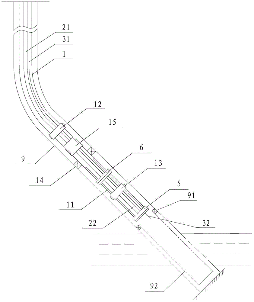
[0042] see figure 1 As shown, the present invention provides a coiled tubing electric ignition string for incubating oil layers in inclined wells. The string is provided with an electric ignition cable 21 and a monitoring cable 31 in the oil pipe 1, and at least one guide and centralizer is provided between the oil pipe 1 sections. 6, and a guide limiter 5 is provided at the bottom end of the oil pipe 1; the electric ignition cable 21 passes through the guide centralizer 6 and is suspended in the oil pipe 1, and the bottom end of the electric ignition cable 21 is connected to the electric ignition 22, the electric igniter 22 is supported in the guide limiter 5; the monitoring cable 31 is suspended in the oil pipe 1 through the guide centralizer 6 and the guide limiter 5 respectively, and monitors The bottom end of the cable 31 protrudes from the oil pipe 1 and is connected with a sensor 32, which may be a temperature and pressure probe of a gas injection well.

[0043] Such a...


PUM


Abstract

The invention provides a deviated well in-situ combustion continuous-tube electric ignition tubular column and an ignition method. The tubular column comprises an oil tube, wherein an electric ignition cable and a monitoring cable are arranged in the oil tube; at least one guiding and centering device is arranged between tube sections of the oil tube; a guiding and limiting stopper is arranged on the bottom end of the oil tube; the electric ignition cable penetrates through the guiding and centering device so as to be suspended in the oil tube; the bottom end of the electric ignition cable is connected with an electric igniter; the electric igniter is supported in the guiding and limiting stopper; the monitoring cable respectively penetrates through the guiding and centering device and the guiding and limiting stopper so as to be suspended in the oil tube; the bottom end of the monitoring cable is stretched out of the oil tube so as to be connected with a sensor. Therefore, air can be heated uniformly during a highly-deviated well ignition process, and the highly-deviated well ignition effect is improved; in addition, the monitoring cable is arranged in the oil tube, so that the monitoring cable cannot be stuck by a packer during the process of pulling out the oil tube, the recycle and the reuse of the monitoring cable are realized, and the investment cost is reduced.

Description

technical field [0001] The invention relates to the technical field of oil recovery by burning oil layers, in particular to an electric ignition string and an ignition method of a coiled tube burning oil layer in an inclined well. Background technique [0002] Burning the oil layer is to inject air or oxygen gas into the oil layer to make it react with a part of the heavy components in the oil layer in the oil layer, and drive the crude oil out of the ground with the heat generated by the reaction and the tail gas of the reaction. This technology is a thermal oil recovery method with obvious technical advantages and potential. It has the characteristics of high oil displacement efficiency, low unit heat cost, and wide reservoir adaptability. [0003] The key to the success of burning the oil layer is the ignition of the oil layer. At present, there are mainly three ignition methods used: spontaneous ignition, chemical ignition and electric ignition, among which electric ign...

Claims


Application Information

Patent Timeline
Patent Type & Authority Applications(China)
IPC IPC(8): E21B43/243
Inventor 张洪君于晓聪彭松良阚长宾黄鹤楠孙鹿恒高峰杨婉玲
Owner PETROCHINA CO LTD
Why Eureka
Try Eureka