Large dynamic signal demodulation device and method of interferometric optical fiber sensor

A fiber optic sensor and signal demodulation technology, which is applied in the direction of using optical devices to transmit sensing components, etc., can solve the problems of increasing hardware complexity and cost, large dynamic range, and increasing requirements for sampling frequency, etc., to reduce signal bandwidth and processing Speed ​​requirements, reducing hardware complexity and cost, and improving the demodulation dynamic range

Active Publication Date: 2014-07-30
NAT UNIV OF DEFENSE TECH
View PDF6 Cites 18 Cited by
  • Summary
  • Abstract
  • Description
  • Claims
  • Application Information

AI Technical Summary

Problems solved by technology

Therefore, in the PGC method and heterodyne demodulation method, improving the dynamic range requires increasing the modulation frequency or heterodyne frequency, so that the requirements for the sampling frequency will increase exponentially, and the technical difficulty and cost of the system will also greatly increase
[0007] The 3×3 coupler multiphase detection method has a large dynamic range, and each sensor needs to add a 3×3 coupler. The optical path structure is complex, and each sensor has three output signals, which requires three optical sampling channels, which also increases the system’s Hardware complexity and cost, unsuitable for large-scale multiplexed interferometric fiber optic sensing systems

Method used


Image

  • Large dynamic signal demodulation device and method of interferometric optical fiber sensor
  • Large dynamic signal demodulation device and method of interferometric optical fiber sensor
  • Large dynamic signal demodulation device and method of interferometric optical fiber sensor

Examples


Embodiment Construction

[0044] The present invention will be described in further detail below in conjunction with the accompanying drawings and specific embodiments.

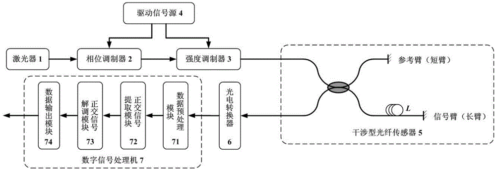
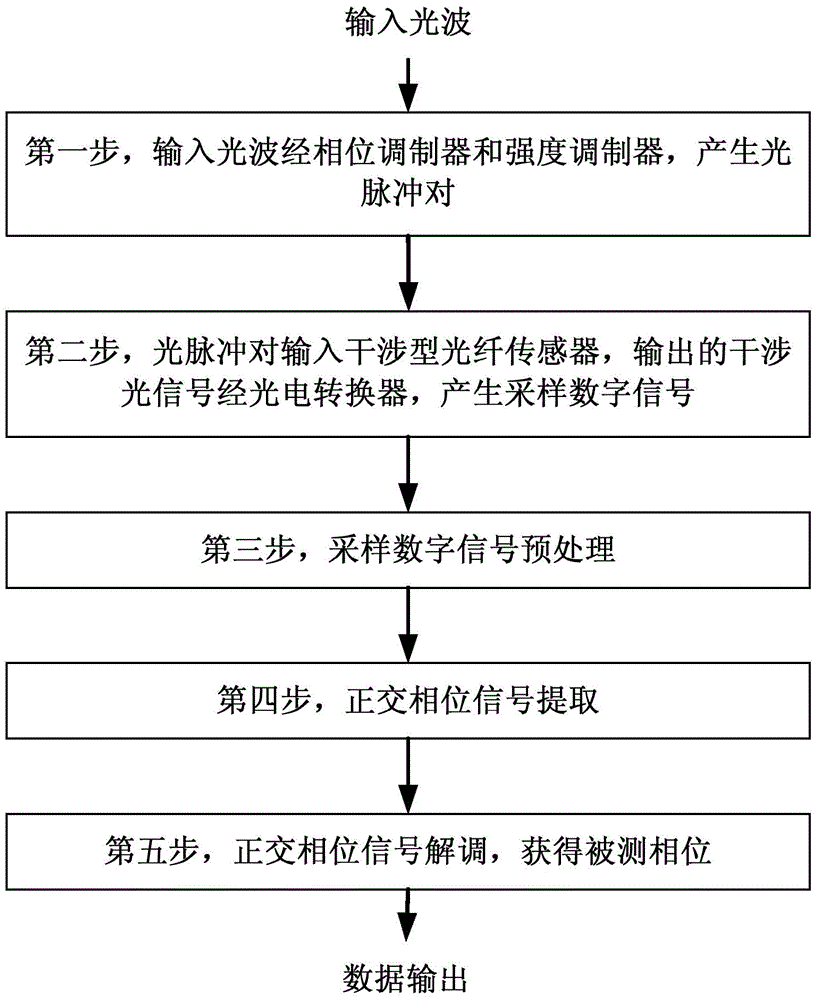
[0045] The schematic diagram of the large dynamic signal demodulation device of the interferometric optical fiber sensor of the present invention is as follows figure 1 As shown, the light emitted by the laser 1 undergoes step wave phase modulation by the phase modulator 2, and then an optical pulse pair is generated by the intensity modulator 3, which is input into the interferometric optical fiber sensor 5 with an unbalanced structure. Interference is formed in the optical fiber sensor 5, and the interference optical signal is subjected to photoelectric detection and analog-to-digital conversion through the photoelectric converter 6, and is input into the digital signal processor 7, and then passed through the data preprocessing module 71, the orthogonal The signal extraction module 72 and the quadrature signal demodulation module 7...


PUM


Abstract

The invention relates to a large dynamic signal demodulation device and method of an interferometric optical fiber sensor. The method is characterized in that after a phase modulator conducts step wave phase modulation on light emitted by a laser, a light pulse pair is generated through an intensity modulator and input into the interferometric optical fiber sensor of an unbalanced structure to form interference, photoelectric detection and analog-to-digital conversion are conducted on an interference light signal through a photoelectric converter, the interference light signal is input into a digital signal processor and then sequentially passes through a data pre-processing module, an orthogonal signal extraction module and an orthogonal signal demodulation module which are located in the digital signal processor, a signal demodulation algorithm is completed, measured phase information is obtained, and finally the information is output through a data output module. The large dynamic signal demodulation device and method of the interferometric optical fiber sensor have the advantages that each sampling point can obtain an effective phase signal output, the demodulation dynamic range is determined by the sampling rate directly, the demodulation dynamic range is widened greatly at the same sampling rate, and the large dynamic signal demodulation device and method are suitable for large dynamic interferometric optical fiber sensors.

Description

technical field [0001] The invention relates to the field of signal demodulation of interference optical fiber sensors, and mainly relates to a large dynamic signal demodulation device and demodulation method suitable for interference optical fiber sensors. Background technique [0002] Optical fiber sensing technology is a new type of sensing technology that developed rapidly with the development of optical fiber and optical fiber communication technology in the 1970s. Different from traditional sensing technology, it uses light wave as the carrier and optical fiber as the medium to perceive and transmit external measured signals. Because the optical fiber is soft, slender, light in weight, small in size, wide in frequency, has good light transmission characteristics and electrical insulation, and the optical fiber itself can be used as a sensitive element, the optical fiber sensor has high sensitivity, anti-electromagnetic interference, and high-voltage resistance. Corros...

Claims


Application Information

Patent Timeline
Patent Type & Authority Applications(China)
IPC IPC(8): G01D5/353
Inventor 姚琼熊水东曹春燕梁迅罗洪杨华勇孟洲
Owner NAT UNIV OF DEFENSE TECH
Why Eureka
Try Eureka