Pressure sensor based on optical fiber FP interferometer and manufacturing method of pressure sensor

The technology of a pressure sensor and a manufacturing method, which is applied to the measurement of fluid pressure using optical methods, and the measurement of force by measuring the change of optical properties of materials when they are stressed, can solve the problems of low reliability, high manufacturing cost, low sensitivity, etc. problem, to achieve the effect of high reliability, simple structure and manufacturing process, and high sensitivity

Active Publication Date: 2014-07-30
SHENZHEN UNIV
View PDF6 Cites 18 Cited by
  • Summary
  • Abstract
  • Description
  • Claims
  • Application Information

AI Technical Summary

Problems solved by technology

Some pressure sensors need to use harmful corrosive gas to corrode the inside of the optical fiber to form an FP cavity during the production process, which will cause great danger to the human body
Some production methods need to use polishing technology to polish the end face of the connected optical fiber, which not only increases the production cost, but also the thickness of the polishing is not easy to control, resulting in low detection sensitivity
In general, the existing pressure sensors based on optical fiber FP interferometer basically have one or more defects as follows: complex structure, complex manufacturing process, high manufacturing cost, low reliability, low sensitivity, etc.

Method used


Image

  • Pressure sensor based on optical fiber FP interferometer and manufacturing method of pressure sensor
  • Pressure sensor based on optical fiber FP interferometer and manufacturing method of pressure sensor
  • Pressure sensor based on optical fiber FP interferometer and manufacturing method of pressure sensor

Examples


Embodiment Construction

[0038] In order to make the object, technical solution and advantages of the present invention clearer, the present invention will be further described in detail below in conjunction with the accompanying drawings and embodiments.

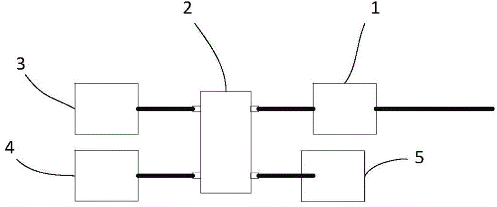
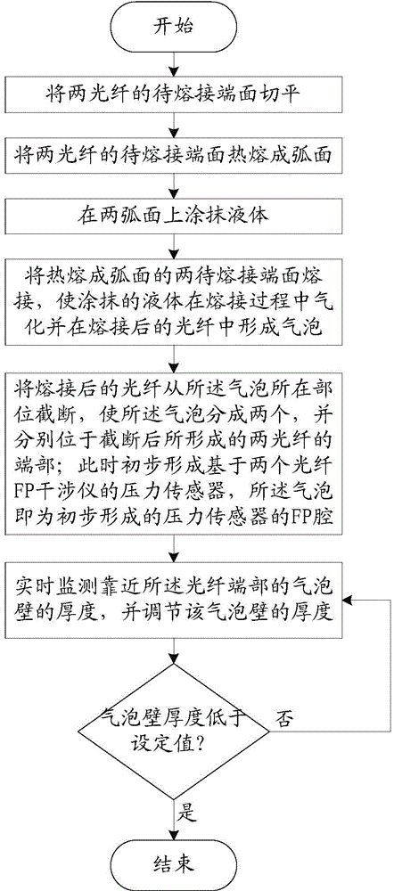
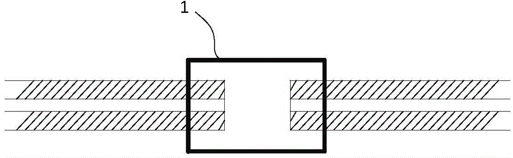
[0039] The pressure sensor based on the optical fiber FP interferometer (hereinafter referred to as the pressure sensor) provided by the present invention realizes the detection of the environmental pressure by making an FP cavity at the end of the optical fiber and detecting the change of the cavity length of the FP cavity. figure 1 A schematic structural diagram of the fabrication device of the pressure sensor is shown. figure 2 A schematic flow chart of manufacturing the pressure sensor using the above-mentioned manufacturing device is shown. first reference figure 1 The manufacturing device of the pressure sensor includes an optical fiber fusion splicer 1, a spectrometer 4, a laser light source 3, and a 3dB coupler 2. The materials required f...


PUM


Abstract

The invention relates to the technical field of optical fiber application, in particular to a pressure sensor based on an optical fiber FP interferometer and a manufacturing method of the pressure sensor. The method comprises the following steps that the end faces to be fused of two optical fibers are coated with liquid and fused, the coating liquid is vaporized in the fusion process, and a bubble is formed in the fused optical fiber; the fused optical fiber is cut off from the portion of the bubble, so that the bubble is divided into two bubbles which are located at the ends of the two cut-off optical fibers respectively; the two pressure sensors based on the optical fiber FP interferometer are formed preliminarily and the bubbles are FP cavities of the preliminarily-formed pressure sensors; the thickness of the bubble walls close to the ends of the optical fibers is monitored in real time and is adjusted, so that the thickness of the bubble walls is lower than a set value. According to the pressure sensor based on the optical fiber FP cavity and manufactured through the technical scheme, a full-optical-fiber structure is adopted and electromagnetic interference can be avoided. Meanwhile, the structure and the manufacturing technology of the pressure sensor are simple and reliability and sensitivity are high.

Description

technical field [0001] The invention relates to the field of optical fiber application technology, in particular to a pressure sensor based on an optical fiber FP interferometer and a manufacturing method thereof. Background technique [0002] FP interferometer (Fabry-Perot interferometer) has a wide range of applications in many fields, one of which is the pressure sensor based on FP interferometer. However, existing pressure sensors based on fiber optic FP interferometers have many defects. Some pressure sensors ensure the detection accuracy, but there are many components, which reduces the overall reliability of the system. In addition, this type of pressure sensor is often bulky, and the processing technology is relatively complicated. This type of sensor does not adapt to the current trend of gradually miniaturizing sensors. Some pressure sensors need to use harmful corrosive gas to corrode the inside of the optical fiber to form an FP cavity during the production pr...

Claims


Application Information

Patent Timeline
Patent Type & Authority Applications(China)
IPC IPC(8): G01L1/24G01L11/02
Inventor 王义平廖常锐刘申
Owner SHENZHEN UNIV
Why Eureka
Try Eureka