
MEMS accelerometer

An accelerometer and acceleration technology, applied in speed/acceleration/shock measurement, acceleration measurement using inertial force, testing/calibration of speed/acceleration/shock measurement equipment, etc., can solve common mode error, accelerometer instability, Problems such as the increase in the variation of differential capacitance can achieve the effect of ensuring resolution, increasing detection capacitance and detection accuracy, and increasing discrimination

Active Publication Date: 2014-07-30
INST OF GEOLOGY & GEOPHYSICS CHINESE ACAD OF SCI
View PDF6 Cites 17 Cited by
  • Summary
  • Abstract
  • Description
  • Claims
  • Application Information

AI Technical Summary

Problems solved by technology

[0007] refer to Figure 4 , when the temperature or stress changes cause the movable comb to deform, the movable gap between the measuring body comb structures in the prior art increases or decreases at the same time, resulting in the cumulative increase of the differential capacitance change, resulting in a common mode error, resulting in acceleration Gauge is unstable under temperature changes or stress changes

Method used


Image

  • MEMS accelerometer
  • MEMS accelerometer
  • MEMS accelerometer

Examples


Embodiment Construction

[0030] Below in conjunction with accompanying drawing, the present invention is described in further detail:

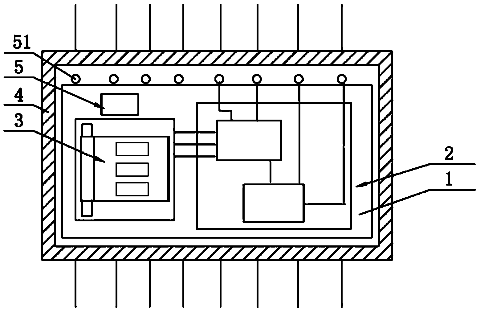
[0031] refer to figure 1 According to a MEMS accelerometer provided by the present invention, it includes: a substrate 1 and an acceleration sensitive chip 3 and an integrated circuit 2 arranged on the substrate 1, the MEMS accelerometer also includes a tube shell 4, and the tube The shell 4 is provided with wiring pins 51 ; the acceleration sensitive chip 3 is connected with the integrated circuit 2 through the tube shell 4 .

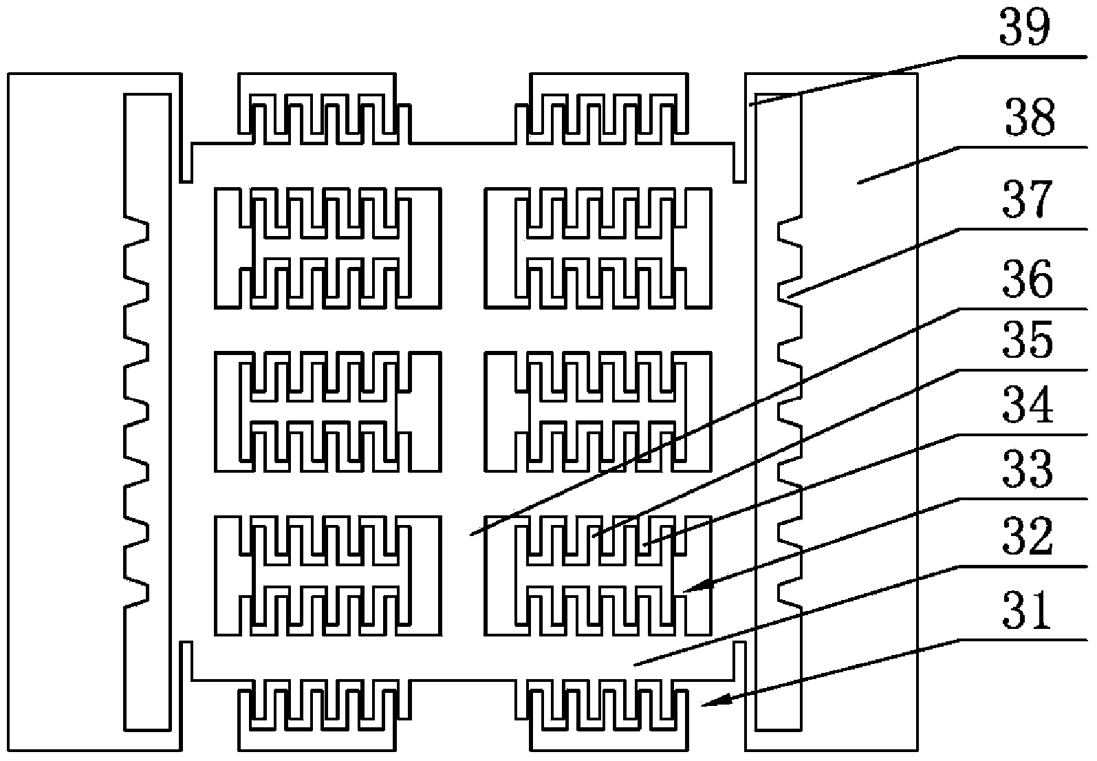
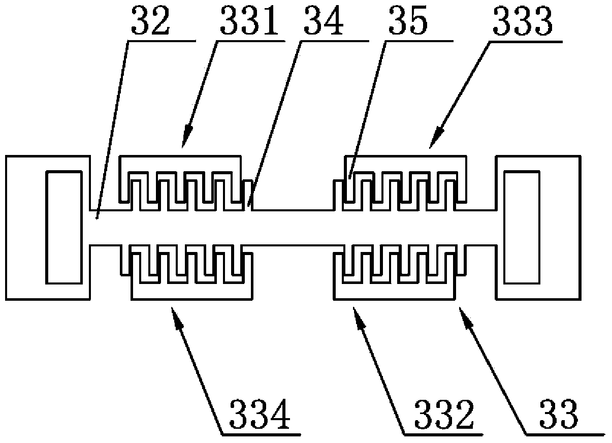
[0032] refer to figure 2 , the acceleration sensitive chip includes a plurality of measuring bodies 31, and each measuring body 31 includes: a mass block 32 and a comb structure 33, and the plurality of measuring bodies 31 are connected to each other through the vertical mass block 36; the comb teeth The structure 33 includes movable comb teeth 34 extending from the mass block 32 , and fixed comb teeth 35 spaced apart from the movable comb t...


PUM


Abstract

An MEMS accelerometer comprises a substrate, an acceleration sensitive chip and an integrated circuit, wherein the acceleration sensitive chip and the integrated circuit are arranged on the substrate, a temperature sensor is further arranged on the substrate and is adjacent to the acceleration sensitive chip, and the acceleration sensitive chip comprises a plurality of measurement bodies. Each measurement body comprises a mass block and a comb tooth structure, wherein the comb tooth structure comprises movable comb teeth extending from the mass block and fixed comb teeth, the movable comb teeth and the fixed comb teeth are arranged at intervals and form a difference detection capacitor, the comb tooth structure is divided into multiple groups, the multiple groups of comb teeth structures are divided into a first part and a second part, the variation direction of movable intervals of the comb tooth structure of the first part and the variation direction of movable intervals of the comb tooth structure of the second part are opposite, and one group of the comb tooth structure and one group of the comb tooth structure of the second part respectively output an electric signal. The MEMS accelerometer resolves the problems that a traditional MEMS accelerometer is large in temperature factor and large in temperature hysteresis.

Description

technical field [0001] The invention relates to a MEMS (micro-electromechanical system) accelerometer, which belongs to the category of MEMS inertial technology. The invention mainly solves many problems of the sensitive chip of the MEMS accelerometer, especially temperature characteristics, measurement accuracy, and environmental adaptability to shock and overload. It can be used as an acceleration sensor for inertial measurement and inertial navigation in the fields of aviation, aerospace, weapons, etc. It can also be used as an acceleration sensor for bridge health monitoring, geological exploration and other fields. Background technique [0002] The principle prototypes of MEMS accelerometers are mostly developed in China, but they are currently facing many difficulties in engineering. Therefore, domestic MEMS accelerometers have not been used on a large scale. The first is the accuracy problem. There is still a large gap between the bias and the stability of the scale f...

Claims


Application Information

Patent Timeline
Patent Type & Authority Applications(China)
IPC IPC(8): G01P15/08B81B7/02G01P21/00
Inventor 薛旭
Owner INST OF GEOLOGY & GEOPHYSICS CHINESE ACAD OF SCI
Learn More