Box-shaped fan-beam antenna

A fan-beam and box-shaped technology, applied in the field of box-shaped fan beam antennas, can solve the problems of unrealizable processing and manufacturing, inability to achieve width-to-narrow ratio, dielectric loss, etc., to avoid the use of power division networks and complex waveguide components, and to reduce occlusion. effect, simple structure

Active Publication Date: 2014-07-30
XIAN INSTITUE OF SPACE RADIO TECH
View PDF2 Cites 14 Cited by
  • Summary
  • Abstract
  • Description
  • Claims
  • Application Information

AI Technical Summary

Problems solved by technology

The fan-shaped beams produced by the current parabolic antennas and box-shaped short backfiring antennas are narrow in width and wide in narrowness, and cannot achieve a large width-to-narrow ratio
When the array antenna works in the lower working frequency band, the current processing and manufacturing level can

Method used


Image

  • Box-shaped fan-beam antenna
  • Box-shaped fan-beam antenna
  • Box-shaped fan-beam antenna

Examples


Embodiment Construction

[0021] The box-shaped fan-beam antenna according to the present invention will be further described in detail below with reference to the accompanying drawings and specific embodiments.

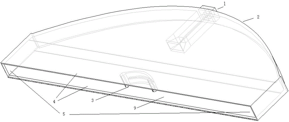
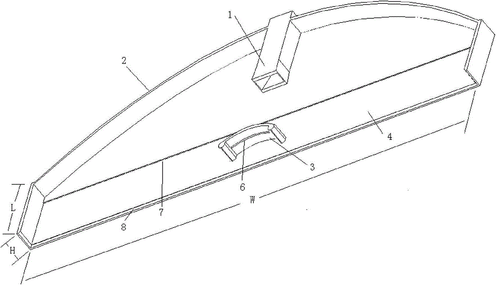
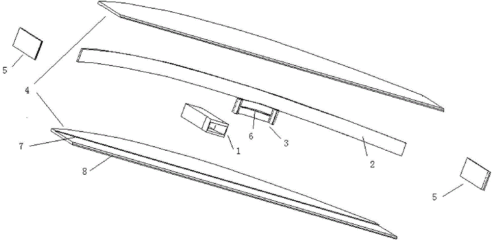
[0022] According to the box-shaped sector beam antenna of the present invention such as figure 1 with figure 2 As shown, it includes: feed horn 1 , cylindrical main reflector 2 , cylindrical secondary reflector 3 , upper and lower cover plates 4 , and left and right baffles 5 .

[0023] The busbars of the cylindrical main reflector 2 and the cylindrical sub-reflector 3 are in the form of Cassegrain antennas. The generatrix of the cylindrical main reflector is a parabola, and the generatrix of the cylindrical sub-reflector is a hyperbola. Of course, the cylindrical generatrix of the cylindrical main reflector 2 and the cylindrical sub-reflector 3 can also be in the form of a ring-focus antenna, but it is not recommended because of its high level of side lobes.

[0024] The left and right b...


PUM


Abstract

The invention provides a box-shaped fan-beam antenna. The box-shaped fan-bean antenna comprises a feed horn, a main cylindrical reflector, an auxiliary cylindrical reflector, an upper cover plate, a lower cover plate, a left baffle and a right baffle. The Cassegrain antenna geometric form is adopted in a bus of the main cylindrical reflector and a bus of the auxiliary cylindrical reflector, the upper side of the main cylindrical reflector, the lower side of the main cylindrical reflector, the left side of the main cylindrical reflector, the right side of the main cylindrical reflector, the upper side of the auxiliary cylindrical reflector, the lower side of the auxiliary cylindrical reflector, the left side of the auxiliary cylindrical reflector and the right side of the auxiliary cylindrical reflector form a box-shaped cavity through the upper cover plate, the lower cover plate, the left baffle and the right baffle respectively, the horn conducting feed on the box-shaped cavity is hidden inside the box-shaped cavity and a waveguide port in the rear portion of the horn serves as a feed port. The box-shaped fan-beam antenna can provide fan beams with a wide pitch (azimuth) range and a narrow azimuth (pitch) range, and is simple in structural form, easy to process and manufacture and very suitable for being applied to millimeter-wave and over-submillimeter-wave frequency bands.

Description

technical field [0001] The invention belongs to the technical field of antennas, and in particular relates to a box-shaped fan-shaped beam antenna. Background technique [0002] In the field of radar and navigation technology, in order to find the target easily, it is usually required to widen the pattern of the other main plane while maintaining a sharp pattern on one main plane, that is, to obtain a fan beam. With the development of radar and navigation technology, the working frequency band is developing towards the millimeter wave and submillimeter wave frequency bands. The fan beam also requires the wider the pitch ( / azimuth) range and the narrower the azimuth ( / pitch) range, the better to achieve Increase the scanning range, improve the resolution, and find the purpose of the target as soon as possible. [0003] The disclosed antennas for generating fan-shaped beams include parabolic cylindrical antennas, box-shaped short backfiring antennas, array antennas, and lens ...

Claims


Application Information

Patent Timeline
IPC IPC(8): H01Q1/36H01Q15/16H01Q13/10
Inventor 卢少鹏万继响
Owner XIAN INSTITUE OF SPACE RADIO TECH
Why Eureka
Try Eureka