
Micro-grid system and networking method based on phase angle droop control

A technology of drooping phase angle and micro-grid, which is applied in the direction of electrical components, circuit devices, AC network circuits, etc., and can solve the problems of large frequency fluctuation range and affecting the stability of micro-grid

Inactive Publication Date: 2014-07-30
GUANGZHOU INST OF ENERGY CONVERSION - CHINESE ACAD OF SCI
View PDF4 Cites 27 Cited by
  • Summary
  • Abstract
  • Description
  • Claims
  • Application Information

AI Technical Summary

Problems solved by technology

[0004] Considering the interconnection of numerous distributed power sources in the microgrid, it is particularly important to perform a reasonable power configuration. In a microgrid system, the reasonable configuration of power should be achieved with the minimum communication cost. Currently, it is more common to use Droop characteristic control method, the control method usually uses frequency droop control to generate a reference signal. This method uses the principle that the distributed power output active power and frequency are linearly related, and the reactive power and voltage amplitude are linearly related. The output characteristics of the inverter are controlled by collecting local feedback information. However, due to the grid connection of many inverters, the frequency fluctuation range is large, which affects the stability of the entire microgrid.

Method used


Image

  • Micro-grid system and networking method based on phase angle droop control
  • Micro-grid system and networking method based on phase angle droop control
  • Micro-grid system and networking method based on phase angle droop control

Examples


Embodiment

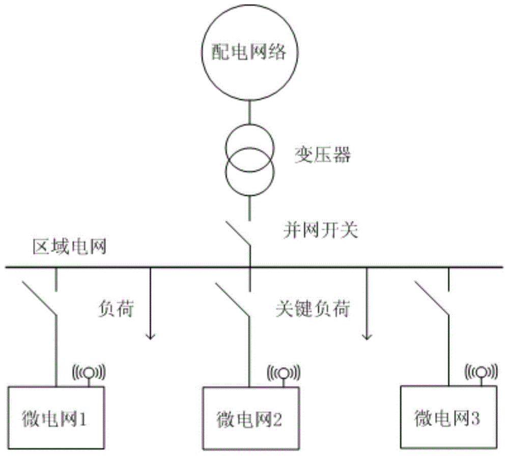
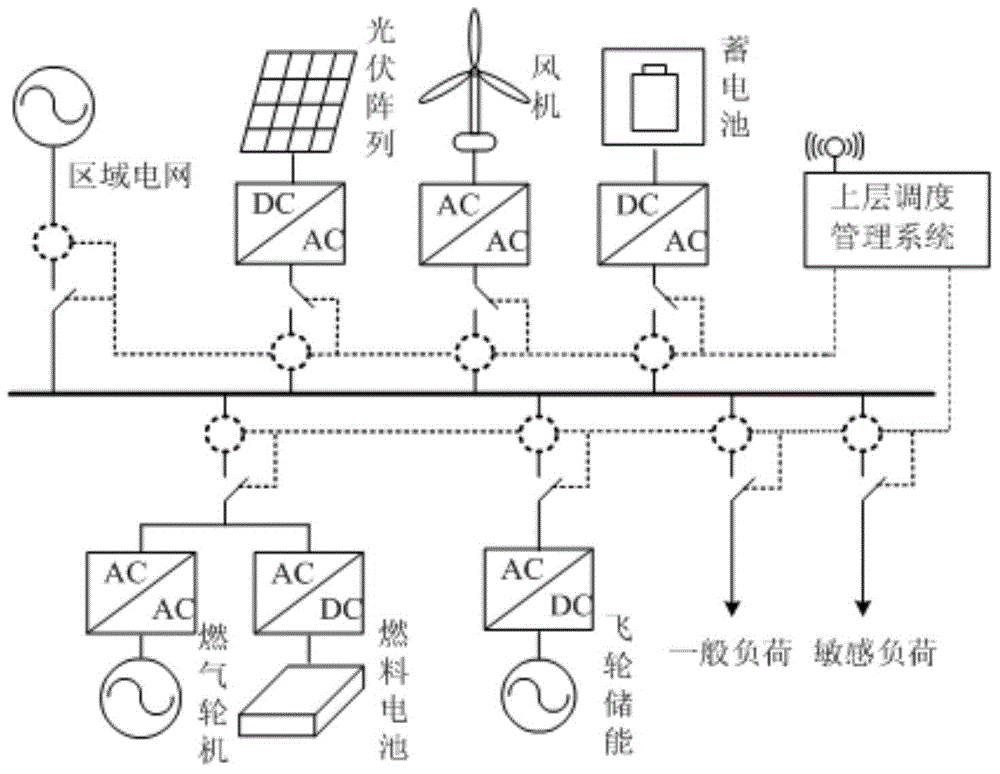
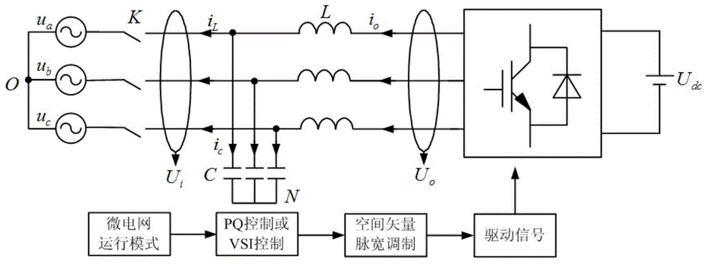
[0043] figure 1 It is a schematic diagram of the microgrid frame structure. Firstly, a regional microgrid is composed of distributed power sources in a small area, and then multiple regional microgrids are operated in parallel to maintain a large-scale energy supply, and excess energy can be injected into the large power grid through a grid-connected switch. In order to provide a unified time reference for multiple microgrids, the GPS synchronous clock is used to generate a common pulse reference. The inverter in the microgrid uses this as a reference to generate a 50Hz pulse with a duty cycle of 50% when the rising edge of the synchronization reference is detected. Square wave pulse, while genlocking, and frequency checking when the rising edge of the next sync reference is detected. Since the microgrid system has a unified synchronous pulse reference, the dynamic adjustment characteristics of each distributed power supply in the microgrid are consistent, thus ensuring that ...


PUM


Abstract

The invention discloses a micro-grid system based on phase angle droop control. The micro-grid system comprises a scheduling system and micro-grid bodies, wherein each micro-grid body is connected with a public grid through a corresponding grid connection switch, and the scheduling system is used for controlling switching-on or switching-off of the grid connection switches so that the micro-grid system can be switched to be in an island mode or in a grid connection mode. When the micro-grid system operates in the island mode, the grid connection switches are switched off, a VSI phase angle droop controller is adopted for a distributed power supply, and voltage and frequency support is provided for the micro-grid bodies. When the micro-grid system operates in the grid connection mode, the grid connection switches are switched on, a PQ controller is adopted for the distributed power supply to output appointed power, and the public grid is used for providing voltage and frequency support for the micro-grid body where the distributed power supply is located. The invention further discloses a micro-grid networking method based on phase angle droop control. According to the micro-grid system and the micro-grid networking method based on phase angle droop control, the utilization rate of the distributed power supply is maximized and meanwhile rational flow of micro-grid energy is achieved.

Description

technical field [0001] The invention relates to the field of microgrids for renewable energy power generation, in particular to a microgrid system and networking method based on phase angle droop control. Background technique [0002] Under the dual pressure of energy crisis and environmental protection, microgrid technology has been widely valued and applied by all walks of life. A microgrid system refers to a regional grid that combines distributed power sources, energy storage units and loads in order to make full use of renewable energy. It can operate in an isolated island mode or be integrated into a large power grid to realize on-site energy development. Utilize, reduce energy transmission loss, and control the energy flow inside the microgrid at the same time, realize the economical and optimal operation of the microgrid system. [0003] The microgrid can be regarded as a regional grid composed of many distributed devices, and the active and reactive power output is...

Claims


Application Information

Patent Timeline
Patent Type & Authority Applications(China)
IPC IPC(8): H02J3/46H02J3/00
Inventor 张继元舒杰黄磊吴昌宏吴志锋
Owner GUANGZHOU INST OF ENERGY CONVERSION - CHINESE ACAD OF SCI
Learn More