Solar power station increasing generating capacity through long afterglow luminescent material lighting slabs

A technology of long afterglow luminescence and luminescent materials, applied in the field of solar power plants, can solve the problem of no power generation and other problems

Active Publication Date: 2014-07-30
NANTONG EOPPLY NEW ENERGY ELECTRIC CO LTD
View PDF7 Cites 1 Cited by
  • Summary
  • Abstract
  • Description
  • Claims
  • Application Information

AI Technical Summary

Problems solved by technology

The solar panels in the existing solar photovoltaic power plants cannot generate current due to the lack of sunlight at night and in rainy days, and the solar photovoltaic power plants have no power generation at night or in rainy days

Method used


Image

  • Solar power station increasing generating capacity through long afterglow luminescent material lighting slabs

Examples


Embodiment 1

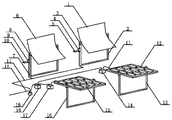
[0028] Sunlight irradiates monocrystalline silicon solar panels to generate current, and the current enters the shunt through conductive wires, controllers, and confluences. Part of the current output from the shunt is input into the power supply network, and the other part of the current is input into the light-emitting panel rotation control device through conductive wires. , Electric adjustment shaft rotation device A and luminous plate rotation control device B, electric adjustment shaft rotation device B, the wired illuminance sensor A receives the light output signal to make the luminescent plate rotation control device A drive the electric adjustment shaft rotation device A to drive the rare earth light storage long afterglow The luminescent material luminescent plate armor stores light and emits light, which increases the power generation of the solar battery plate armor. The wired illuminance sensor B receives the light output signal to make the light-emitting panel ro...

Embodiment 2

[0030] The sunlight irradiates the polysilicon solar panel to generate current, and the current is input into the shunt through the conductive wire, the controller, and the confluence, and part of the current output from the shunt is input into the power supply network, and the other part of the current is input into the light-emitting panel rotation control device A, electric motor through the conductive wire Adjustment shaft rotation device A and luminous plate rotation control device B, electric adjustment shaft rotation device B, outdoor illuminance sensor A receives the light output signal to make luminous plate rotation control device A drive the electric adjustment shaft rotation device A to drive the rare earth nanometer long afterglow luminescent material The light-emitting plate armor stores light and emits light, which increases the power generation of the solar battery plate armor. The outdoor illuminance sensor B receives the light output signal to make the lumines...


PUM


Abstract

The invention relates to a solar power station increasing the generating capacity through long afterglow luminescent material lighting slabs and belongs to the technical field of new energy application. Solar cell panels are irradiated with sunlight, so that current is generated and input into a shunt through an electric lead, a controller and a junction station, one part of the current output from the shunt is input to a supply network, the other part of the current is input to a first lighting slab rotation control device, a first electric adjusting shaft rotation device, a second lighting slab rotation control device and a second electric adjusting shaft rotation device through electric leads. A first illuminance sensor receives illumination output signals so as to enable the first lighting slab rotation control device to drive the first electric adjusting shaft rotation device to drive the first long afterglow luminescent material lighting slab to store and emit light, and the generating capacity of the first solar cell panel is increased. A second illuminance sensor receives illumination output signals so as to enable the second lighting slab rotation control device to drive the second electric adjusting shaft rotation device to drive the second long afterglow luminescent material lighting slab to store and emit light, and the generating capacity of the second solar cell panel is increased.

Description

technical field [0001] The invention relates to a solar power station with a long afterglow luminescent material luminescent plate to increase the amount of power generation, and belongs to the technical field of new energy applications. Background technique [0002] The proportion of coal-fired power generation in China used to reach 70%. A large amount of coal-fired power generation emits carbon dioxide, sulfur dioxide, other harmful gases and various particulate matter into the air, forming smog and acid rain, which damages the ecological environment. In order to reduce the amount of coal burned and reduce the proportion of coal-fired power generation, attention has been paid to photovoltaic power generation that does not emit any pollutants into the air during the power generation process. At the end of 2008, the cumulative installed capacity of large-scale photovoltaic power plants in China was only 1MW, and it increased to 109MW at the end of 2009. , increased to 4400M...

Claims


Application Information

Patent Timeline
Patent Type & Authority Applications(China)
IPC IPC(8): H02S20/32
CPCY02E10/50
Inventor 缪同春
Owner NANTONG EOPPLY NEW ENERGY ELECTRIC CO LTD
Why Eureka
Try Eureka