
Control apparatus and method for controlling a DC voltage converter

A control device, a technology for DC voltage, applied in output power conversion devices, high-efficiency power electronic conversion, conversion of DC power input to DC power output, etc., can solve problems such as danger, transformer saturation, and reduction of excitation inductance

Active Publication Date: 2014-07-30
ROBERT BOSCH GMBH
View PDF5 Cites 5 Cited by
  • Summary
  • Abstract
  • Description
  • Claims
  • Application Information

AI Technical Summary

Problems solved by technology

At the same time it is possible that the magnetic flux reserve disappears during the generation of the PWM control signal and that an excessively high magnetizing current leads to a saturation of the primary side of the transformer of the push-pull converter and a resulting reduction of the magnetizing inductance, which may be due to the high The current on the primary side is another potential hazard for the semiconductor switches on the primary side

Method used


Image

  • Control apparatus and method for controlling a DC voltage converter
  • Control apparatus and method for controlling a DC voltage converter
  • Control apparatus and method for controlling a DC voltage converter

Examples


Embodiment Construction

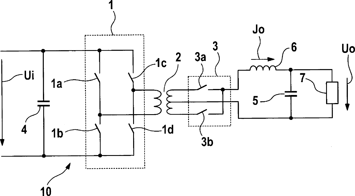
[0020] figure 1 A schematic diagram of a DC voltage converter 10 is shown. The DC voltage converter 10 comprises a transformer 2 having a primary side winding and a secondary side winding which is divided into two sections by means of an intermediate tap. The transformer 2 can be designed, for example, for converting a high voltage into a low voltage and can have, for example, a winding ratio between the primary-side and secondary-side windings of higher than 1, in particular, for example, 10:1. In particular, the winding ratio of the two secondary-side winding sections can be 1, ie the two secondary-side winding sections have the same number of windings.

[0021] The primary-side winding of the transformer can be fed by the two output terminals of the four-quadrant regulator 1 . In this case, the four-quadrant regulator 1 can have, for example, four switching devices 1 a , 1 b , 1 c , 1 d in the form of a full bridge circuit. The switching devices 1 a , 1 b , 1 c , 1 d can...


PUM


Abstract

The invention relates to an activation apparatus (20) for a galvanically decoupled DC voltage converter having a synchronous rectifier, comprising a signal generating device (22), which is designed to generate control signals (22c, 22d) for switch devices of the synchronous rectifier and a reference current signal (22b), a first comparator device (23), which is coupled to the signal generating device (22), and which is designed to detect the secondary-side output current (Jo) of the synchronous rectifier, compare it to the reference current signal (22b) and generate a current control signal in dependence on the comparison, and a pulse width modulation device (25), which is coupled to the signal generating device (22) and the first comparator device (23) and which is designed to generate pulse width modulated activation signals (25a); for the switch devices of the synchronous rectifier on the basis of the control signals (22c, 22d) and the current control signal, wherein the signal generating device (22) is furthermore designed to reduce the reference current signal (22b) within a first predetermined timespan to a predetermined reference current threshold.

Description

technical field [0001] The invention relates to a control device and a method for controlling a DC voltage converter, in particular a push-pull converter in the form of a full bridge circuit. Background technique [0002] Usually synchronous rectifier circuits are used in push-pull converters in the form of full-bridge or half-bridge circuits for DC conversion, for example for supplying the low-voltage on-board electrical system of vehicles. For this purpose, the power semiconductor switches used both on the primary side and on the secondary side, for example MOSFETs, must be protected against overvoltage or excessive current levels. [0003] To control the active synchronous rectifier circuit, the microprocessor supplies pulse width signals, which are converted, for example via pulse width modulation elements, into corresponding PWM control signals for the individual semiconductor switches. When the push-pull converter is switched off, discontinuous current operation (DCM,...

Claims


Application Information

Patent Timeline
Patent Type & Authority Applications(China)
IPC IPC(8): H02M3/335H02M1/36H02M1/00
CPCH02M1/36H02M3/33592Y02B70/10H02M1/0025H02M3/3378
Inventor S·科赫F·利布朗S·宾哈克T·普里斯特尔M·策勒E·许克尔S·米勒田健R·博哈特R-P·贝格曼
Owner ROBERT BOSCH GMBH
Learn More