Method and device for simulating thin-strip continuous casting technical process

A continuous casting process and thin strip technology, which is applied in the field of simulating the thin strip continuous casting process, can solve the problems of inability to verify the production feasibility of the product, and cannot be taken out quickly, and achieve good compliance

Active Publication Date: 2014-08-06
BAOSHAN IRON & STEEL CO LTD
View PDF6 Cites 16 Cited by
  • Summary
  • Abstract
  • Description
  • Claims
  • Application Information

AI Technical Summary

Problems solved by technology

But its disadvantages are: (1) Due to the high cooling rate of the water-cooled copper mold of this device, the molten steel will be solidified at the sprue of the molten pool soon after it is injected, and it is difficult to continue to inject molten steel, and the molten pool will often be blocked during the test. (2) The device cannot be taken out quickly after the solidified sample is obtained, and the follow-up cooling process of the strip continuous casting simulation cannot be performed, and the production feasibility of the product under the strip continuous casting process cannot be verified

Method used


Image

  • Method and device for simulating thin-strip continuous casting technical process
  • Method and device for simulating thin-strip continuous casting technical process
  • Method and device for simulating thin-strip continuous casting technical process

Examples


Embodiment

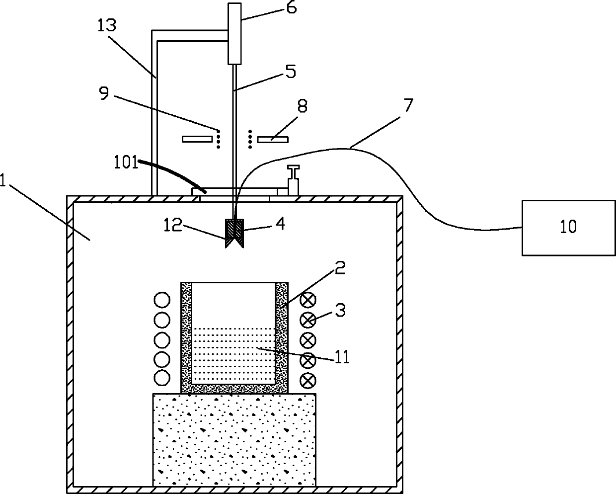
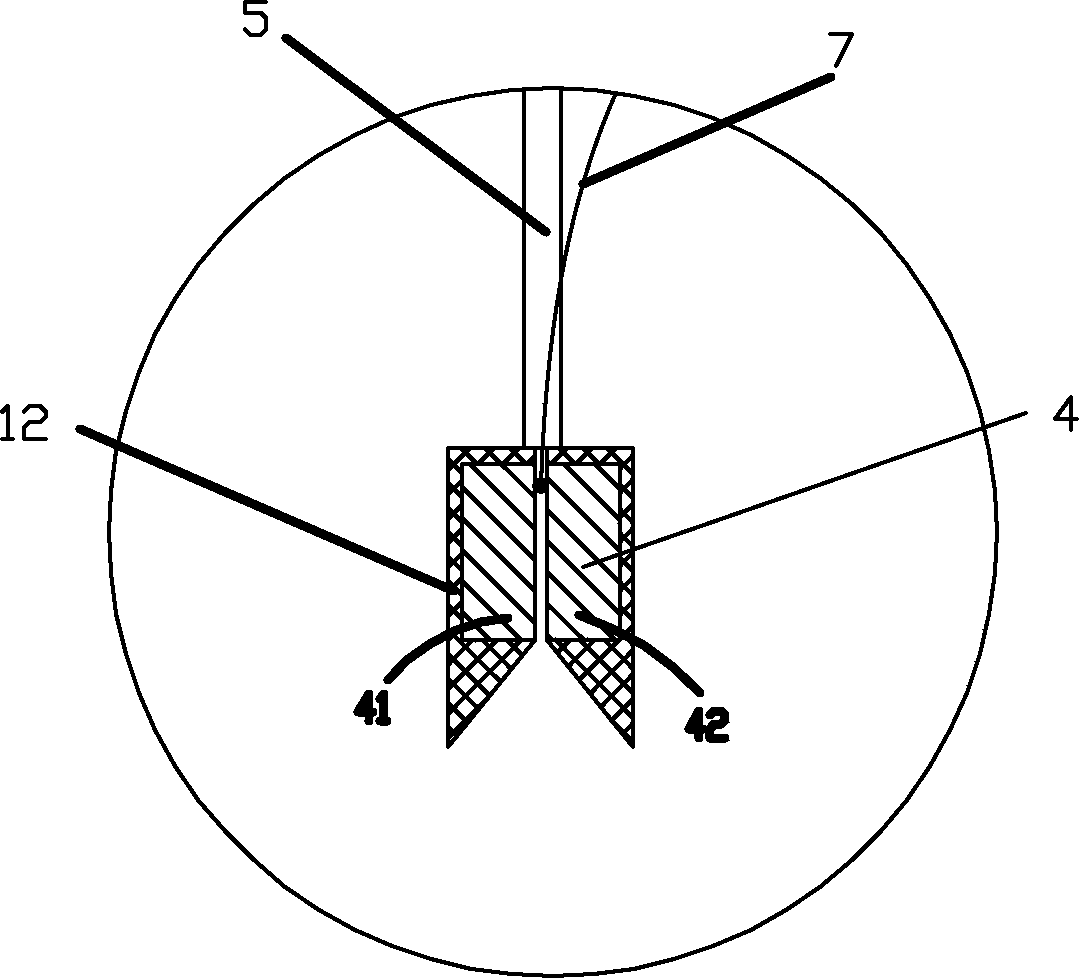
[0040] The cooling mold of the present invention is composed of two cooling molds (copper blocks) with a certain gap in the middle, and the gap distance is 2.5 mm, which is used to simulate the roll gap of the thin strip continuous casting crystallization roll. A temperature-measuring thermocouple is installed in the gap between the two cooling molds, and the graduation number of the thermocouple is S-type. When the molten steel solidifies in the gap of the cooling mold, the thermocouple can be directly covered and embedded in the solidified sample, and the thermocouple is connected with the data acquisition system. , the temperature change of the solidified sample can be monitored during the experiment. The two cooling molds (copper blocks) can be separated quickly. Except for the inner surface in contact with the molten steel, the other sides and bottom surfaces of the cooling mold are covered with heat-insulating refractory materials. The refractory material is alumina to en...


PUM


Abstract

The invention discloses a method and a device for simulating a thin-strip continuous casting technical process. The method comprises the following steps: arranging a melting crucible in a confined space or a vacuum space, filled with a protective gas, and arranging cooling dies above the melting crucible; mounting the cooling dies on a driving rod; during a test, driving the cooling dies by the driving rod to be inserted in the molten steel in the melting crucible; after the cooling dies are inserted in the molten steel, quickly filling a gap between the two cooling dies with the molten steel; under the chilling function of the cooling dies, solidifying to form a solidified shell; mounting cooling nozzles in position rightly opposite to the surface of the solidified shell; utilizing a temperature thermocouple to record temperature change of the solidified shell in the cooling process; when reaching a set cooling temperature, closing the cooling nozzles; starting an induction coil arranged outside the melting crucible to quickly heat the solidified sample and then preserve heat, setting the sample temperature during the heat preservation according to the coiling temperature of the test design, and utilizing the induction coil to preserve heat and slow cooling to simulate the cooling slowing process of the thin-strip continuous casting product after online coiling.

Description

technical field [0001] The invention relates to iron and steel metallurgy, in particular to a method and device for simulating the thin strip continuous casting process. Background technique [0002] In recent years, the near-net-shape continuous casting technology has developed rapidly, especially represented by the twin-roll strip continuous casting process. In the process of twin-roll thin strip continuous casting, after the molten steel in the molten pool composed of two crystallization rolls and side sealing plates contacts the crystallization rolls, it solidifies rapidly in a very short period of time to form a solidified shell, which is formed after casting and rolling by twin rolls Cast strip, which is then secondary cooled and coiled to form finished coils. There is a big difference between the thin strip continuous casting process and the traditional strip steel production process. In addition to studying the influence of thin strip continuous casting sub-rapid so...

Claims


Application Information

Patent Timeline
Patent Type & Authority Applications(China)
IPC IPC(8): B22D11/16
Inventor 王成全王秀芳于艳方园
Owner BAOSHAN IRON & STEEL CO LTD
Why Eureka
Try Eureka