Double-end-face over-locating fixture

A technology of over-positioning and double-end faces, which is applied in the direction of expanding the mandrel, etc., can solve the problems of unstable process dimensions, etc., and achieve the effect of small elastic deformation recovery, control of plastic deformation, and ensure stability

Active Publication Date: 2014-08-06
西安双特智能传动有限公司
View PDF7 Cites 7 Cited by
  • Summary
  • Abstract
  • Description
  • Claims
  • Application Information

AI Technical Summary

Problems solved by technology

[0003] The purpose of the present invention is to overcome the defects of the prior art and provide a double-end over-positioning fixture to solve the problem of unstable process dimensions caused by plastic deformation and elastic deformation of thin-walled parts during machining

Method used


Image

  • Double-end-face over-locating fixture

Examples


Embodiment Construction

[0015] Below in conjunction with accompanying drawing the present invention is described in further detail:

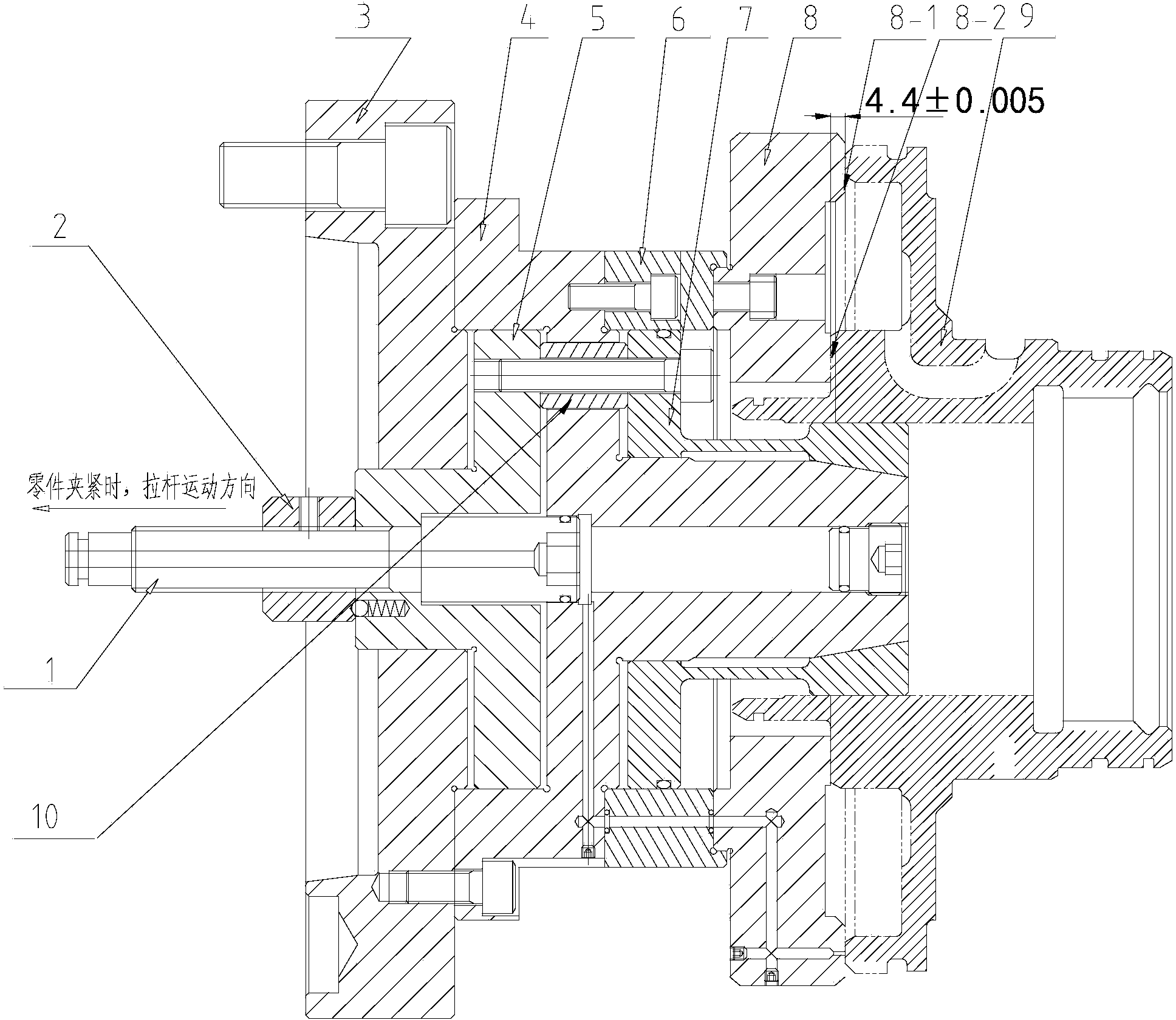
[0016] Such as figure 1 As shown, its main structure consists of the following components:

[0017] Pull rod: connected to the hydraulic cylinder to transmit the pulling force;

[0018] Connecting plate: Cooperate with the tie rod to transmit the pulling force of the tie rod, and at the same time ensure the centering installation of the mandrel;

[0019] Mandrel: It is fixedly connected with the machine table, and the end face is connected with a support plate, which can adjust the axial positioning;

[0020] Support plate: The end surface is connected with a positioning pad, and its inner hole cooperates with the expansion sleeve to ensure the centering movement of the expansion sleeve along the axial direction;

[0021] Over positioning pad: The over positioning pad is connected to the connection plate, and the axial position can be adjusted according to the thick...


PUM


Abstract

The invention provides a double-end-face over-locating fixture. The double-end-face over-locating fixture comprises a pull rod, a connecting disk and a mandrel, wherein the pull rod is connected with a hydraulic cylinder of a machine tool, the connecting disk is connected with the pull rod in a matched mode for transmitting the pull force of the pull rod, and the mandrel is mounted on the connecting disk in a sleeved mode and fixedly connected with a machine tool workbench. An over-locating pad used for axially locating and limiting a workpiece is fixedly mounted on the mandrel. The connecting disk is also connected with an expansion sleeve, and the mandrel is sleeved with the expansion sleeve. The expansion sleeve is pulled through the pull rod, the expansion sleeve expands in an inner hole of the workpiece and tightens the workpiece, and the workpiece is pulled backwards to generate certain controllable axial deformation; before the workpiece is turned, the expansion sleeve is pulled backwards to make a part be tightened in the radial direction and the end face be located in the axial direction; meanwhile, since the over-locating pad is adopted to locate and limit the workpiece, the problem that process dimensions are unstable because the thin-walled part generates uncontrollable elastic deformation and molding deformation in the turning process under the influence of back pull force generated by pulling the expansion sleeve backwards and the extrusion force generated in the cutting process of a blade is avoided, a process dimensional tolerance and a related form and location tolerance are guaranteed, and the stability of machining dimensions is also guaranteed.

Description

technical field [0001] The invention relates to the field of product processing, in particular to a double-end over-positioning fixture. Background technique [0002] At present, for the problem that the plastic deformation and elastic deformation generated in the machining process of thin-walled parts affect the process size tolerance and the accuracy of related shape and position tolerances, it is generally to modify the tool compensation by estimating the deformation of the part, or modify the program coordinates Parameters compensate the deformation to meet the dimensional tolerance requirements. However, this cannot fundamentally control the deformation. The following problems still exist in the processing process: First, the deformation generated by different batches of blanks is not the same, and the compensation parameters need to be constantly changed to meet the processing requirements. The compensation parameters need to be determined by multiple experimental meas...

Claims


Application Information

Patent Timeline
Patent Type & Authority Applications(China)
IPC IPC(8): B23B31/40
CPCB23B31/40
Inventor 王军柯瓦泽王亚锋于显爱崔宝峰张涛
Owner 西安双特智能传动有限公司
Why Eureka
Try Eureka