
Laser cutting machine

A laser cutting machine and frame technology, applied in laser welding equipment, welding/cutting auxiliary equipment, auxiliary devices, etc., can solve the problems of thermal damage to parts, low work efficiency, and difficult removal of debris, so as to prevent position changes, The effect of fast feeding speed

Active Publication Date: 2014-08-06
ZHEJIANG JINGRI LIGHTING TECH
View PDF10 Cites 11 Cited by
  • Summary
  • Abstract
  • Description
  • Claims
  • Application Information

AI Technical Summary

Problems solved by technology

Patent application publication number CN 103212821 A. The Chinese invention patent with the application publication date of 2013.07.24 discloses a laser cutting machine, which mainly solves the problem of heat generated by the laser cutting machine in the process of processing small diameter pipes in the prior art. Heat damage, debris is not easy to remove, including the cutting head and the front water guide system, the motor of the front water guide system is connected by a coupling, a bush and a water guide pipe, one end of the bush is located in the coupling, and the other end Sealed connection with the water guide pipe, the end of the water guide pipe close to the bushing has a water inlet, the water inlet is connected with the sealed bearing of the automatic water supply system, the outer diameter of the water guide pipe is smaller than the inner diameter of the pipe to be processed, and the end of the water guide away from the bushing is inserted into the inside of the pipe to be processed The technical scheme solves this problem well and can be used in the industrial production of laser wet cutting processing
[0003] However, when the existing laser cutting machine is cutting, it is found that the cutting effect is not good enough, and the work efficiency is relatively low.

Method used

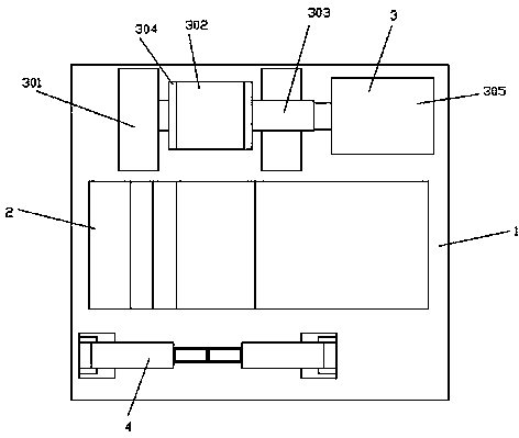
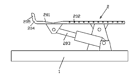
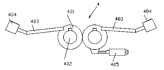

Image

  • Laser cutting machine
  • Laser cutting machine
  • Laser cutting machine

Examples


Embodiment Construction

[0024] The following descriptions are only preferred embodiments of the present invention, and do not limit the scope of the present invention.

[0025] example, see attached figure 1 , 2 , 3; a laser cutting machine, including a frame, the frame is provided with a pipe feeding device, a workpiece conveying device for conveying the pipe conveyed by the pipe feeding device, and a pipe conveying device conveyed by the workpiece conveying device. Rotary clamping device for clamping, laser head device for cutting the pipe clamped by the rotary clamping device, and unloading device, the pipe feeding device includes a raceway or conveyor chain on which the pipe is placed It is conveyed into the laser cutting machine, and then the workpiece conveying device conveys the pipe in the laser cutting machine, and aligns the pipe while conveying, so that the center line of the pipe is consistent with the conveying direction, and then the pipe is rotated by the clamping device. Clamp, use ...


PUM


Abstract

The invention discloses a laser cutting machine. The laser cutting machine comprises a machine frame, wherein a pipe feeding device, a workpiece conveying device, a rotation clamping device, a laser head device and a discharging device are arranged on the machine frame, the workpiece conveying device is used for conveying pipes conveyed from the pipe feeding device, the rotation clamping device is used for clamping the pipes conveyed from the workpiece conveying device, and the laser head device is used for cutting the pipes clamped by the rotation clamping device. The discharging device comprises an installation base, a tilting mechanism arranged on the installation base, a chucking mechanism which is arranged on the installation base and is located at the back of the tilting mechanism in the conveying direction of the pipes, and a clamping device which is arranged on the installation base and is located in front of the tilting mechanism in the conveying direction of the pipes. The laser cutting machine is simple in structure, convenient to use, good in pipe cutting effect and high in work efficiency.

Description

technical field [0001] The invention relates to the technical field of cutting machines, in particular to a laser cutting machine. Background technique [0002] Laser cutting machine, which can generate a laser beam. When the laser beam is irradiated on the surface of the workpiece to be processed, it can release energy, so that the irradiated part of the workpiece is melted and evaporated, thereby achieving the purpose of cutting and engraving, with high precision, cutting Fast, not limited to cutting pattern restrictions, automatic typesetting saves material, smooth incision, low processing cost, etc. Patent Application Publication No. CN 103212821 A. The Chinese invention patent with the application publication date of 2013.07.24 discloses a laser cutting machine, which mainly solves the problem that the heat generated by the laser cutting machine in the process of processing small diameter pipes in the prior art may cause damage to parts. Thermal damage, the problem tha...

Claims


Application Information

Patent Timeline
IPC IPC(8): B23K26/38B23K26/70B23K37/04
CPCB23K26/0823B23K26/38B23K26/702B23K37/00B23K2101/06
Inventor 汤燕军叶少军
Owner ZHEJIANG JINGRI LIGHTING TECH
Learn More