Mechanical arm

A technology of manipulator and mechanical arm, applied in the direction of manipulator, claw arm, chuck, etc., can solve the problems of low efficiency, complex manipulator structure, large space occupation, etc. The effect of easy structure

Active Publication Date: 2014-08-06
GUANGZHOU DAZHENG ADVANCED MATERIAL TECH CO LTD
View PDF10 Cites 17 Cited by
  • Summary
  • Abstract
  • Description
  • Claims
  • Application Information

AI Technical Summary

Problems solved by technology

[0002] At present, in the welding, assembly, die-casting and other mechanical processing production processes, it is generally necessary to take and discharge the workpiece, but in many mechanical processing production processes, manual operations are used to carry out the material taking and discharging operations. The operation is inconvenient, the production efficiency is low, and it is easy to damage and dirty the workpiece, and the automatic production can ensure the high precision, high quality and high efficiency requirements of the product, so the automatic manipulator is widely developed and applied to the molding machine and machine tool , assembly lines, die-casting machines and other equipment or devices to perform operations such as moving objects and sucking workpieces, but most of the existing technologies use clamps and jaw devices to clamp workpieces, which leads to large and heavy manipulators. Not conducive to gripping small workpieces
[0003] Among them, in the field of casting, especially on die-casting machines or hydraulic machines, since there are four columns in the workpiece processing area, it is difficult for ordinary manipulators to intelligently pass through the four columns to directly take or unload materials. The degree of automation is not high, but they can intelligently wear The structure of the manipulator passing through four columns is also relatively complex, occupying a large space, and the telescopic stroke is short
[0004] The Chinese invention patent application number is 201310012515.9, and the patent name is "Automatic Production Line Manipulator", which discloses an automatic production line manipulator, which includes a motor mounting plate, a driving motor, multiple guide rods, a lifting plate, a cylinder, and a rotating arm shaft , Manipulator mounting seat, multiple guide rods are vertically fixed on the motor mounting plate, the lifting plate is slidingly connected with multiple guide rods, the output end of the cylinder is connected to the lifting plate, the shaft of the rotating arm is vertically rotated on the lifting plate, and the driving motor The output end of the output end is connected to the lower end of the rotating arm shaft through a triangular shaft drive. The manipulator mounting base is fixed on the upper end of the rotating arm shaft. A mechanical arm is installed on the manipulator mounting base. There is a suction nozzle fixing seat, the bottom of the suction nozzle fixing seat is provided with a nozzle head, and a triangular shaft is provided between the lifting plate and the motor mounting plate. It does not have telescopic function and is not suitable for the processing area surrounded by columns in the production line, and the setting angle of the robot arm is relatively single
[0005] The Chinese invention patent application number is 201310192985.8, and the patent name is "a vertical loading and unloading manipulator". , the vertical servo motor drives the vertical moving column to move up and down; at the same time, the rotation control device can control the rotation of the manipulator box along the rotation axis; Manual loading and unloading; although this invention can effectively reduce manpower and production costs, and avoid personal safety accidents in the production process, the telescopic stroke of the manipulator is too short, and there is only one manipulator, which is too single and inefficient, so it is not suitable for the requirements On an automated production line with fast moving speed and large processing range

Method used


Image

  • Mechanical arm
  • Mechanical arm
  • Mechanical arm

Examples


Embodiment

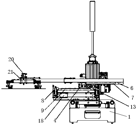
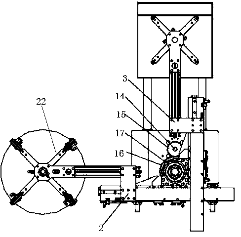
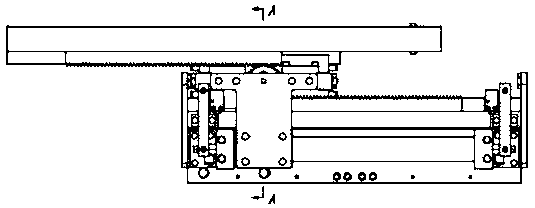
[0036] like figure 1 , figure 2 , image 3 and Figure 4 Shown, a kind of manipulator comprises base 1, and is located on base 1 pneumatic swing angle cylinder 14, rotating mechanism, telescoping mechanism and sucker device, and described driving device is connected with rotating mechanism, is used to drive rotating mechanism to rotate, and The telescoping mechanism is connected with the rotating mechanism, the rotating mechanism drives the telescopic mechanism to rotate, the telescopic mechanism is connected with the suction cup device, the telescoping mechanism includes a mechanical arm, and the mechanical arm is two intersecting mechanical arms arranged at 90 degrees, They are the first mechanical arm 2 and the second mechanical arm 3 respectively, and each of the mechanical arms corresponds to a slide plate 4 and a manipulator mount 5 connected to the rotating mechanism, and the upper linear guide rail 6 is arranged on the lower surface of each mechanical arm and the u...


PUM


Abstract

The invention discloses a mechanical arm. The mechanical arm comprises a base, a driving device, a rotating mechanism, a telescopic mechanism and a material taking device, wherein the driving device, the rotating mechanism, the telescopic mechanism and the material taking device are arranged on the base. The driving device is connected with the rotating mechanism and used for driving the rotating mechanism to rotate. The telescopic mechanism is connected with the rotating mechanism and driven by the rotating mechanism to rotate. The telescopic mechanism is connected with the material taking device. The telescopic mechanism comprises at least one mechanical arm body, sliding boards and mechanical arm installation bases connected with the rotating mechanism, wherein the sliding boards correspond to the mechanical arm bodies one to one. The mechanism arm bodies are connected with the mechanical arm installation bases through the sliding boards. The sliding boards are controlled to slide by a drive part. The mechanical arm is capable of automatically taking and placing materials, easy and convenient to operate, high in production efficiency, wide in machining range and large in telescopic range.

Description

technical field [0001] The invention relates to a mechanical device, in particular to a manipulator. Background technique [0002] At present, in the welding, assembly, die-casting and other mechanical processing production processes, it is generally necessary to take and discharge the workpiece, but in many mechanical processing production processes, manual operations are used to carry out the material taking and discharging operations. The operation is inconvenient, the production efficiency is low, and it is easy to damage and dirty the workpiece, and the automatic production can ensure the high precision, high quality and high efficiency requirements of the product, so the automatic manipulator is widely developed and applied to the molding machine and machine tool , assembly lines, die-casting machines and other equipment or devices to perform operations such as moving objects and sucking workpieces, but most of the existing technologies use clamps and jaw devices to cl...

Claims


Application Information

Patent Timeline
Patent Type & Authority Applications(China)
IPC IPC(8): B25J18/02B25J15/06
Inventor 卓奇周郭新辉林真富
Owner GUANGZHOU DAZHENG ADVANCED MATERIAL TECH CO LTD
Why Eureka
Try Eureka