Device promoting reasonable distribution of coal gas flow in shaft furnace

A technology of distribution device and gas flow, applied in shaft furnaces, furnaces, furnace types, etc., can solve the problems of low airflow velocity in the surrounding pipes and loop pipes, clogging of fine dust in the surrounding pipes, and reduced metallization rate, etc., and achieve reasonable distribution of gas flow. , the effect of increasing the residence time and improving the utilization rate

Inactive Publication Date: 2014-08-06
NORTHEASTERN UNIV
View PDF2 Cites 7 Cited by
  • Summary
  • Abstract
  • Description
  • Claims
  • Application Information

AI Technical Summary

Problems solved by technology

In actual production, Baosteel’s COREX3000 shaft furnace introduced the Areal Gas Distribution (AGD) technology invented by Siemens VAI, that is, two AGD tubes are installed at the surrounding tube position of the shaft furnace, and the no gas formed spontaneously under the AGD tube during the process of lowering the charge is used. The charging gas channel leads the gas to the center of the shaft furnace. However, in actual operation, it is found that the amount of gas leading to the center is difficult to control, and the excessive development of the central air flow will easily lead to low airflow velocity around the surrounding pipe, insufficient blast kinetic energy, and the surrounding pipe is easy to be small. Dust clogging causes uneven air distribution in the furnace, lower metallization rate, and affects production efficiency

Method used


Image

  • Device promoting reasonable distribution of coal gas flow in shaft furnace
  • Device promoting reasonable distribution of coal gas flow in shaft furnace
  • Device promoting reasonable distribution of coal gas flow in shaft furnace

Examples


Embodiment 2

[0033] The specific implementation of a device for promoting the reasonable distribution of gas flow in the shaft furnace in Embodiment 2 will be described in detail below.

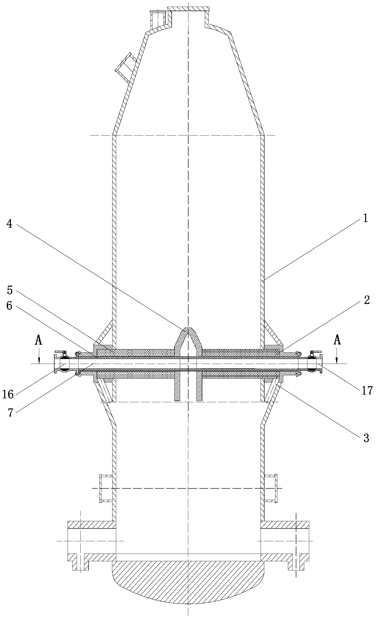
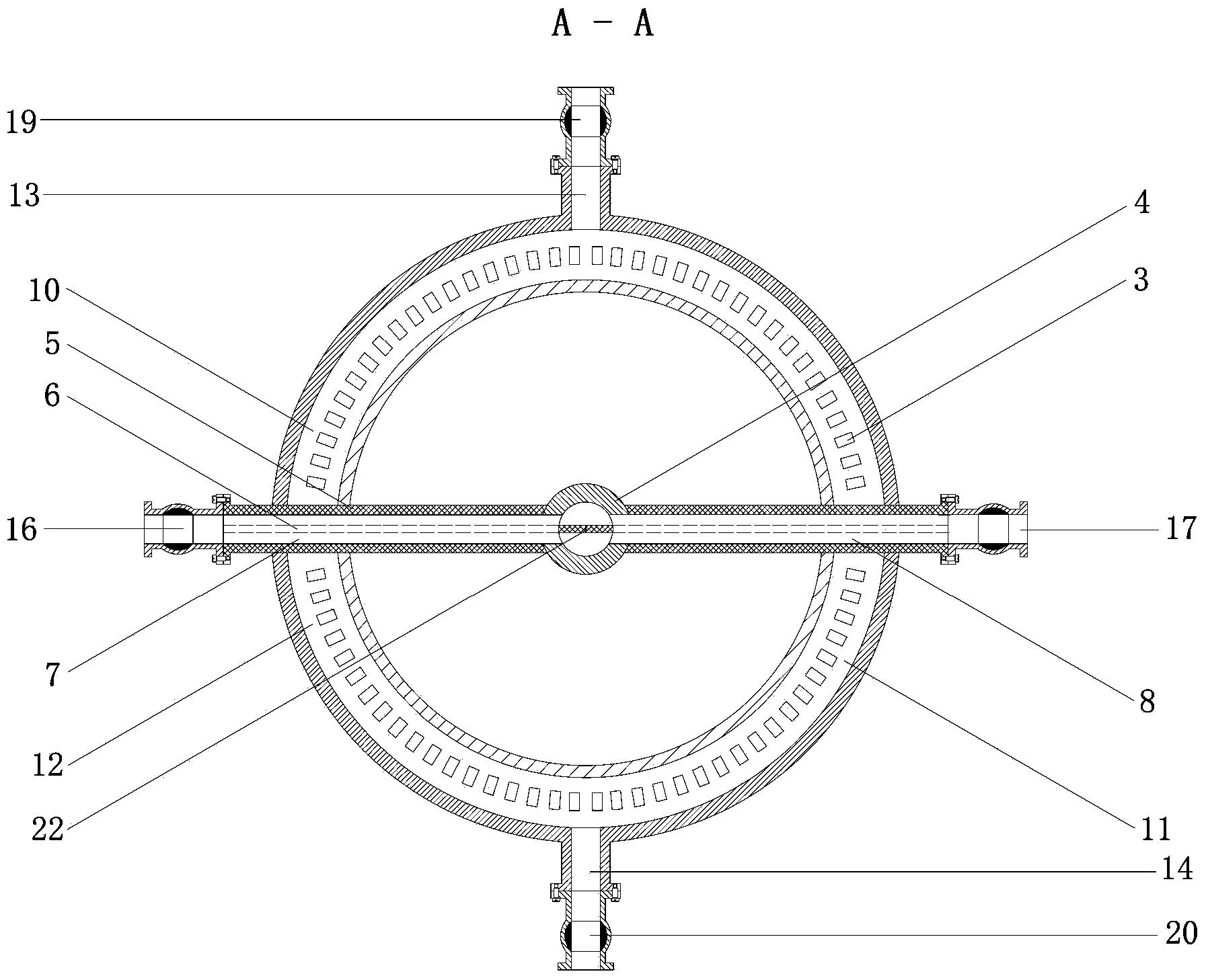
[0034] Figure 4 It is a structural schematic diagram of the embodiment 2 "a device for promoting the reasonable distribution of gas flow in the shaft furnace", Figure 5 for Figure 4 The C-C cross-sectional view mainly includes the shaft furnace body 1, the conical gas distribution device 4 inside the shaft furnace, and three internal gas supply pipes 7, 8, and 9 that are 120° along the circumferential direction, corresponding to the internal gas pipes connected to the internal gas pipes. Air supply flow regulating valves 16, 17, 18, three internal air supply pipes divide the surrounding pipe into three mutually independent surrounding pipe air supply areas 10, 11, 12, and the three independent surrounding pipe air supply areas are respectively connected with The three surrounding pipe gas supply pipe...


PUM


Abstract

The invention discloses a device promoting reasonable distribution of coal gas flow in a shaft furnace. The device is provided with a surrounding pipe and a slot pipe, and is characterized by further comprising 2-3 inner gas supply pipes and a tapered gas distributing device; each two adjacent inner gas supply pipes form an angle of 120 DEG C or an angle of 180 DEG C mutually; the inner gas supply pipes extend into the center of the shaft furnace; the outer opening of each inner gas supply pipe is communicated with a coal gas generating device; the inner opening of the inner gas supply pipe is communicated with the tapered gas distributing device at the central position in the shaft furnace; the outside of the inner gas supply pipes separates the surrounding pipe into 2-3 independent surrounding pipe gas feeding areas; a surrounding pipe gas supply pipe communicated with the outer coal gas generating device is arranged in each surrounding pipe gas feeding area. The device enables coal gas extending into the shaft furnace to be distributed more uniformly, and improves utilization ratio of the coal gas remarkably.

Description

technical field [0001] The invention relates to equipment used in the technical field of non-blast furnace ironmaking, in particular to a device for promoting the reasonable distribution of gas flow in a shaft furnace. Background technique [0002] Smelting reduction refers to the process of smelting and producing molten iron in non-blast furnace ironmaking methods. Its technical idea is to develop an ideal smelting process that does not require iron ore agglomeration or expensive metallurgical coke, and can produce high-quality molten iron without polluting the environment. [0003] The pre-reduction shaft furnace is located above the melting and gasifier. The materials added to the shaft furnace are pellets, lump ore and flux (limestone and dolomite). In addition, in order to avoid the bonding of iron-containing materials and maintain sufficient gas permeability of the bed, it is necessary to Add a certain amount of coke. The reduced gas at around 800°C to 850°C is blown...

Claims


Application Information

Patent Timeline
Patent Type & Authority Applications(China)
IPC IPC(8): C21B13/02
Inventor 张丽娟游洋罗志国邹宗树周恒李海峰
Owner NORTHEASTERN UNIV
Why Eureka
Try Eureka