Method and device for detecting electric spindle tension and broken yarn in spinning machine

A yarn break detection and spinning frame technology, applied in the field of electricity, can solve the problems of complex mechanism of yarn breakage detection method and inability to detect yarn tension on the spindle of spinning frame, so as to achieve good forming, reduce roving loss, and reduce the difference between spindles. Reduced effect

Inactive Publication Date: 2014-08-06
PACIFIC MECHATRONIC GRP
View PDF6 Cites 13 Cited by
  • Summary
  • Abstract
  • Description
  • Claims
  • Application Information

AI Technical Summary

Problems solved by technology

[0003] The object of the present invention is to provide a method for detecting spindle tension and yarn breakage in a spinning frame. The method for detecting spindle tension and yarn breakage in a spinning frame is to solve the problem of the inability to detect the yarn on the spindle of a spinning frame in the prior art. The technical problem of the tension situation, and the technical problem of the complex mechanism in the yarn breakage detection method

Method used


Image

  • Method and device for detecting electric spindle tension and broken yarn in spinning machine
  • Method and device for detecting electric spindle tension and broken yarn in spinning machine
  • Method and device for detecting electric spindle tension and broken yarn in spinning machine

Examples


Embodiment 1

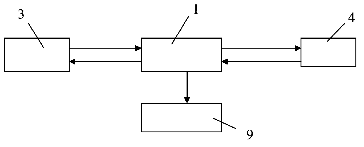
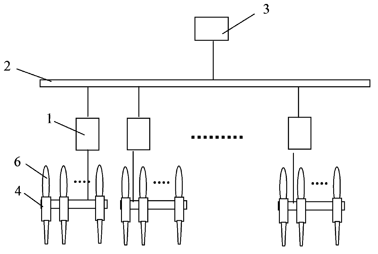
[0020] The electric spindle tension and yarn break detection method in the spinning frame of the present invention includes the process of using a motor to independently drive a spindle, the motor includes an input end, and the input end is connected to a drive circuit through a control line, wherein , in the process of using the motor to drive the spindle alone, the current value passing through the motor or the speed value of the motor is detected in real time, and the tension of the yarn on the spindle is judged according to the change of the current value or the change of the speed value Variety.

[0021] Further, when it is detected that the current value drops suddenly during the spinning operation of the spindle, it is judged that the yarn on the spindle is broken.

[0022] Or, when it is detected that the speed value suddenly rises during the spinning operation of the spindle, it is judged that the yarn on the spindle is broken.

[0023] Alternatively, the current val...


PUM


Abstract

The invention discloses a method for detecting electric spindle tension and broken yarn in a spinning machine. The method comprises the following steps: a motor independently drives a spindle, the input end of the motor is connected with a drive circuit; a detection circuit is used for detecting the current value and the speed value passing through the motor in real time, and the change of the tension on a yarn is judged according to the change of the current value or the speed value; during the spindle spinning operation process, the fact that the yarn on the spindle is broken is judged when the current value suddenly decreases or the speed value suddenly increases. The detection circuit and the drive circuit are connected with a control circuit; the control circuit reads the current value and the speed value and outputs a signal or adjusts the output of a control circuit according to the change of the current value or the speed value. The method is implemented through the control circuit. The control circuit comprises a programmable controller and a digital signal processing system. According to the yarn tension, the following commands are outputted including stopping feeding roving in the case of yarn breakage, stopping operation of an electric spindle or decelerating operation, so that cop is formed in an excellent manner, the difference between spindles is reduced, after yarn is broken, feeding of the roving is automatically stopped, and loss of the roving is reduced.

Description

Technical field: [0001] The present invention relates to the field of electricity, in particular to the electronic control and detection technology for textile machinery, in particular to the detection technology of the yarn tension on the electric single spindle of the spinning frame, and in particular to the detection of the tension of the electric spindle and the broken yarn in the spinning frame Methods and Apparatus. Background technique: [0002] The spinning frame is widely used in the textile industry, and the roving is drawn, twisted and spun into a spun yarn. The spinning frame includes a feeding mechanism, a drafting mechanism, a twisting and winding mechanism and a winding and forming mechanism. Among them, the twisting and winding mechanism includes a spindle and a traveler. The bobbin for collecting yarn is arranged on the spindle and rotates with the spindle. When the spindle rotates, the yarn sliver drives the traveler to rotate. A twist is added to the dra...

Claims


Application Information

Patent Timeline
Patent Type & Authority Applications(China)
IPC IPC(8): D01H13/32D01H13/14
Inventor 陈兴强过明言李光荣陈斌袁松鹤陆亚明陆秀梅王丹
Owner PACIFIC MECHATRONIC GRP
Why Eureka
Try Eureka