
Compact liquid-tube vacuum tube water heater compatible with phase change heat storage function

A technology of vacuum tube water heater and phase change heat storage, which is applied in the field of solar thermal energy, can solve the problems that it is difficult to form a secondary natural circulation water heater, the parts of the water heater are damaged, and it is difficult to install a phase change heat storage device, so as to achieve weight reduction and liquid circulation. The effect of short path and high heat collection efficiency

Inactive Publication Date: 2014-08-06
秦三根
View PDF0 Cites 3 Cited by
  • Summary
  • Abstract
  • Description
  • Claims
  • Application Information

AI Technical Summary

Problems solved by technology

[0007] 1. The surface of the electric heating tube in the water heater is easy to corrode, easy to scale, easy to leak electricity after the electric heating tube is damaged, and there is a hidden danger of dry burning without water;
[0008] 2. Limited by the structure of the all-glass vacuum heat collecting tube, it is difficult to form a secondary natural circulation water heater with good water quality;
[0009] 3. Limited by the structure of the all-glass vacuum heat collecting tube, it is difficult to install a phase change heat accumulator in the vacuum tube
[0010] 4. In the case of water shortage in the water heater tank or long-term use of hot water, it is easy to overheat, which will cause great damage to the components in the water heater

Method used


Image

  • Compact liquid-tube vacuum tube water heater compatible with phase change heat storage function
  • Compact liquid-tube vacuum tube water heater compatible with phase change heat storage function
  • Compact liquid-tube vacuum tube water heater compatible with phase change heat storage function

Examples


Embodiment Construction

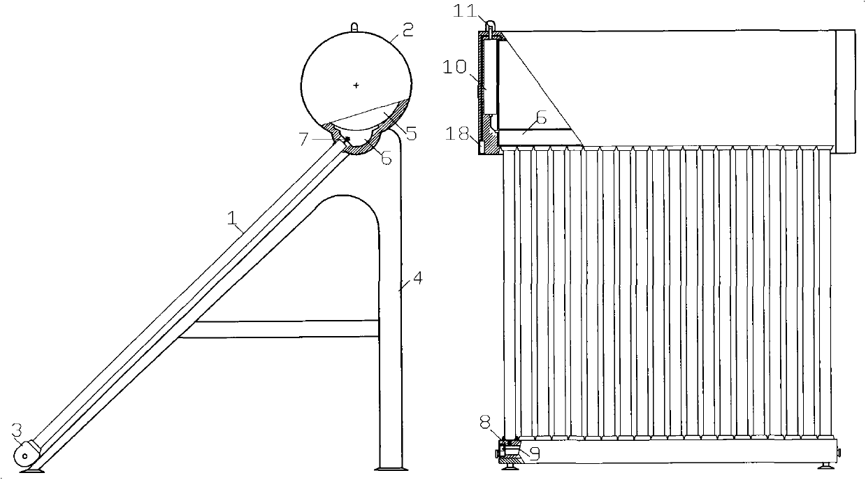
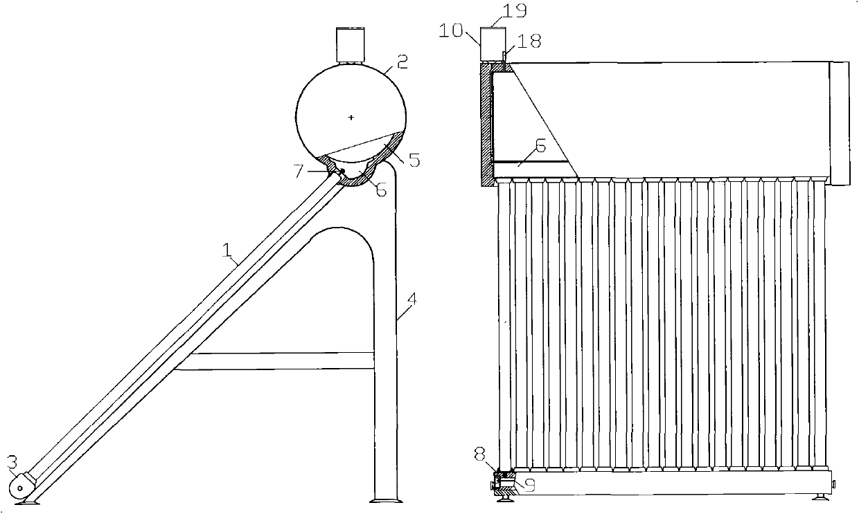
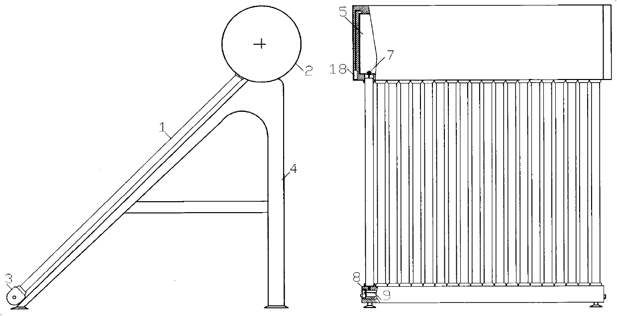
[0038]figure 1 , figure 2 It is an embodiment of the secondary circulation water heater of the present invention. In the figure, the thermal insulation water tank (2) is on the top, and the multifunctional header (3) is on the bottom, which are respectively fixed on the bracket (4), and the heat transfer liquid ( 16) The upper end communicates with the heat transfer liquid pipe interface (7) of the jacketed heat exchanger (6), the lower end communicates with the inline header (8) of the multifunctional header (3), and the electric heating tube (9) is installed in the header (8) In the flow channel, the pressurized liquid replenisher (10) is installed on the side of the heat preservation water tank (2) higher than the jacket heat exchanger (6), the lower end is connected with the jacket heat exchanger (6), and the upper end is connected to the overpressure Protection and de-expansion device (11). Take off the overpressure protection and de-expansion device (11), and heat-cond...


PUM


Abstract

A compact liquid-tube vacuum tube water heater compatible with a phase change heat storage function is available in four types, namely phase change heat storage, non-phase-change heat storage, single natural cycle heat storage, and double natural cycle heat storage. The compact liquid-tube vacuum tube water heater comprises liquid-tube vacuum tubes (1), an insulation water tank (2), a multifunctional header (3), a support (4) and the like. The upper end of a heat transfer liquid tube (16) in each liquid-tube vacuum tube (1) is communicated with a heat transfer liquid tube connector (7) of the insulation water tank (2) through a seal ring; the lower end of every heat transfer liquid tube (16) is communicated with a flow passage of a header tube (8) in the multifunctional header (3) through a seal ring. An electric heating tube (9) is mounted in the flow passage of the header tube (8) of the multifunctional header (3). A temperature control fan (18) is mounted on the insulation water tank (2). The liquid-tube vacuum tubes (1) include liquid-tube vacuum collector tubes and liquid-tube phase change heat storage vacuum collector tubes; the two types of tubes are universal, compatible and exchangeable and can be mixed for use. The compact liquid-tube vacuum tube water heater has the functions of freezing prevention, adjustable water temperature of the lower end of the water tank, controllable temperature of the upper end of the water tank and the like.

Description

technical field [0001] The invention is a compact liquid tube type vacuum tube water heater compatible with the phase change heat storage function in the solar thermal field. Background technique [0002] Known existing compact water heater types include all-glass vacuum tube solar water heaters, all-glass heat pipe solar water heaters, and heat-pipe vacuum tube solar water heaters. About 90% of them are all-glass vacuum tube solar water heaters. The main problems are: [0003] The hot water in the vacuum tube of the all-glass vacuum tube solar water heater occupies about 20% of the volume of the distributed water tank and cannot be used, and the heat utilization rate is low. It is easy to freeze and crack, and it is easy to explode the tube when it is suddenly cooled. The vacuum tube breaks and leaks, and the water heater cannot be used. [0004] The all-glass heat pipe solar water heater, although there is no water in the vacuum tube and antifreeze, because the condensati...

Claims


Application Information

Patent Timeline
IPC IPC(8): F24J2/24F24J2/34F24J2/46F24S10/70
CPCY02E10/44F24S60/30F24S10/45F24S60/00F24S60/10
Inventor 秦三根
Owner 秦三根
Learn More