Eureka AIR delivers breakthrough ideas for toughest innovation challenges, trusted by R&D personnel around the world.

Loop radial shearing N-step phase-shift interferometer based on polarization phase-shift principle

A technology of loop radial shear and phase shift interference, which is applied in the field of loop radial shear N-step phase shift interferometer based on the principle of polarization phase shift, which can solve the complex structure of the four-step space phase shift and the increased difficulty in the installation and adjustment process. , affecting the measurement accuracy and other issues, to achieve the effect of improving data processing speed and algorithm accuracy, small measurement dynamic range, and low measurement accuracy

Inactive Publication Date: 2014-08-06
SICHUAN UNIV
View PDF3 Cites 8 Cited by
  • Summary
  • Abstract
  • Description
  • Claims
  • Application Information

AI Technical Summary

Problems solved by technology

However, since the four groups of light paths of the four interferograms generated by this structure pass through different parts of the optical element, it will cause problems such as uneven light distribution and inaccurate phase shift, which will affect its measurement accuracy.
In addition, the four-step spatial phase shift in the patent "Common Optical Path Shearing Interferometer Based on Four-step Spatial Phase Shift" (patent application number: 201010034142.3) has a complex structure and a large number of devices, which makes the installation and adjustment process more difficult

Method used


Image

  • Loop radial shearing N-step phase-shift interferometer based on polarization phase-shift principle

Examples


Embodiment Construction

[0024] The present invention will be described in detail below by examples in conjunction with the accompanying drawings. It is necessary to point out that the following examples are only used for further description of the present invention, and cannot be interpreted as limiting the protection scope of the present invention, and those skilled in the art make some non-essential improvements to the present invention according to the above-mentioned content of the present invention And adjustments still belong to the protection scope of the present invention.

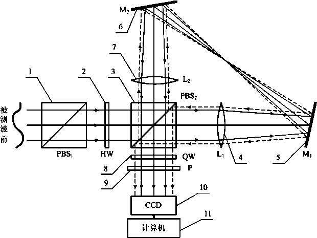
[0025] Such as figure 1 As shown, the ring direction shear N-step phase shift interferometer based on the principle of polarization phase shift includes: polarizing beam splitter PBS 1 1. 1 / 2 wave plate HW2, polarizing beam splitter PBS 2 3. Lens L 1 4. Mirror M 1 5 and M 2 6. Lens L 2 7. Composed of 1 / 4 wave plate QW8, analyzer P9, photocoupler CCD10 and computer 11. Polarizing Beamsplitter Prism PBS 1 1 and 1 / 2 ...


PUM


Abstract

The invention provides a loop radial shearing N-step phase-shift interferometer based on the polarization phase-shift principle. The loop radial shearing N-step phase-shift interferometer is composed of a polarization modulation system, a loop radial shearing system, an N-step phase-shift system and an imaging system. Measured wavefront generated after a measured light beam passes through a measured element enters the polarization modulation system and then is changed into linearly polarized light. The linearly polarized light enters the loop radial shearing system and then is divided into two beams of orthogonal linear polarized light in the horizontal polarization direction and the vertical polarization direction respectively, and the two beams of orthogonal linear polarized light pass through the N-step phase-shift system to form two beams of circular polarized light in the levorotation direction and the dextrorotation direction respectively. A rotation polarization analyzer achieves N-step phase shift. Finally, the imaging system collects N interference fringe diagrams, and then the phase-shift algorithm is adopted for analyzing the interference fringe diagrams to calculate the wavefront phase position of the reconstructed light beams. According to the loop radial shearing N-step phase-shift interferometer based on the polarization phase-shift principle, no reference mirrors are needed, a light path structure is simple, and anti-vibration capability is good; the N-step phase-shift technology is adopted for recovering the wavefront, and phase position extraction data processing speed and algorithm precision are improved.

Description

technical field [0001] The present invention relates to the technical field of Cyclic Radial Shearing Interferometry (CRSI, Cyclic Radial Shearing Interferometry) for detecting the wavefront generated by light beams or optical elements, in particular to a circular radial shearing method based on the principle of polarization phase shift step-shift interferometer. Background technique [0002] Wavefront sensors that measure wavefront phase based on the principle of interferometry have attracted widespread attention due to their high spatial resolution and high measurement accuracy. Typical interferometric wavefront sensors include shear interferometers, point-diffraction interferometers, and the like. [0003] As a wavefront sensor that can directly restore the wavefront phase, the point diffraction interferometer has been widely used in adaptive optics systems (Optics Express.15(21):13745-13756). However, due to the use of a pinhole filter in the optical path, the light en...

Claims


Application Information

Patent Timeline
IPC IPC(8): G01J9/02G02B27/28
Inventor 李大海章辰邱佳琪赵光远王琼华
Owner SICHUAN UNIV
Why Eureka
Eureka Blog
Learn More