Field-programmable gate array based real-time synchronous data acquisition intellectual property core

An intellectual property core, real-time synchronization technology, applied in electrical digital data processing, instruments, etc., can solve problems such as low efficiency, low speed, and inability to synchronize in real time

Active Publication Date: 2014-08-06
JILIN UNIV
View PDF3 Cites 10 Cited by
  • Summary
  • Abstract
  • Description
  • Claims
  • Application Information

AI Technical Summary

Problems solved by technology

[0006] The purpose of the present invention is to propose a real-time synchronous data acquisition IP core based on FPGA, which overcomes the low efficiency, low speed and inability to synchronize in real time of traditional sensor data acquisition, realizes parallel processing of sensor data acquisition, and achieves relative High acquisition speed requirements and real-time synchronization characteristics of sensor data acquisition

Method used


Image

  • Field-programmable gate array based real-time synchronous data acquisition intellectual property core
  • Field-programmable gate array based real-time synchronous data acquisition intellectual property core
  • Field-programmable gate array based real-time synchronous data acquisition intellectual property core

Examples


Embodiment 1

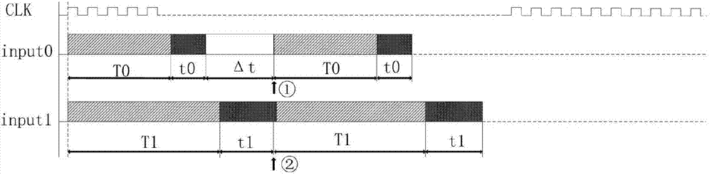
[0052] The real-time synchronous sequential logic of embodiment 1 system

[0053] refer to figure 1 , which shows the real-time synchronous timing logic diagram of the system. In the figure, there are three kinds of signals, among which CLK is the clock signal of the system, input0 is the acquisition signal input from sensor 1 to the CPU, and input1 is the acquisition signal input from sensor 2 to the CPU. The present invention utilizes the parallel feature of FPGA, and any sensor 1 and sensor 2 in the sensor self-defined IP core module are independent IP cores, conforming to the AVALON bus, and the two IP cores can simultaneously collect data when a clock front arrives.

[0054] T0 is the time required for sensor 1 to collect data, T1 is the time required for sensor 2 to collect data, t0 is the transmission time for sensor 1 to send the collected data to the CPU for data processing, and t1 is the time for sensor 2 to send the collected data to The transmission time of the C...

Embodiment 2

[0055] The data processed by the CPU comes from various sensors, and the data of each sensor is performed on the same clock edge, that is, the CPU receives all the sensor data at the same time, so the present invention realizes the real-time synchronization of sensor data collection. This timing diagram simply introduces the situation of the two sensors. Due to the large interface resources of the FPGA, there are many types of sensors that can be loaded, but they can all achieve real-time synchronization. Embodiment 2 NIOS II processor system architecture

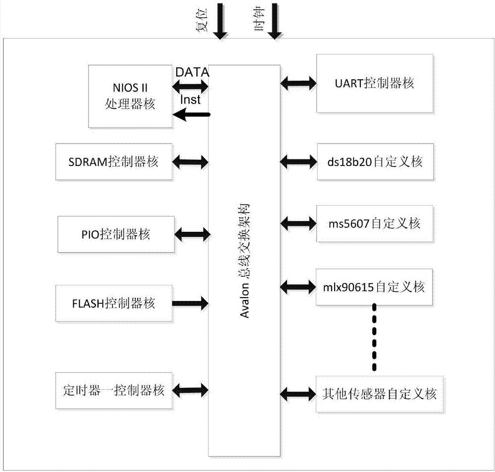
[0056] refer to figure 2 , which shows the hardware design scheme used in this design. The design divides the hardware architecture into three parts, including basic IP core modules, peripheral IP core modules, and sensor custom IP core modules. The NIOS II processor system is based on the premise of the Avalon bus switching architecture. The port of the NIOS II processor is the main port, and the ports of the other peri...

Embodiment 3

[0060] Example 3 temperature and pressure sensor ms5607 custom IP core

[0061] refer to Figure 6 , the figure shows the interface protocol of the temperature and air pressure sensor ms5607. According to the chip manual of ms5607, it can be known that seven steps are required to collect data from this sensor. The first six steps are as follows: Figure 6 As shown, there are corresponding command bytes. The order of data reading is as follows: read 8 parameter values ​​(C0~C7) first, then read the value of D1, and finally read the value of D2.

[0062] refer to Figure 7 , the figure shows the interface timing of temperature and air pressure sensor ms5607 initialization. It can be seen from the timing diagram that the CSB is pulled low to enable the bus; the value of SDI is judged at the rising edge of the clock, and the value of SDI is the value of the command byte of the steps that need to be completed. At this time, the value of SDI is 0x1e, which is a reset command ;A...


PUM


Abstract

The invention relates to a field-programmable gate array based real-time synchronous data acquisition intellectual property core, belonging to the technical field of internet-of-things application. The intellectual property core comprises a basic IP (Internet Protocol) core module, an external IP core module and a sensor user-defined IP core module, wherein the sensor user-defined IP core module comprises a temperature-air pressure sensor user-defined IP core, an infrared temperature measurement sensor user-defined IP core, a temperature testing sensor user-defined IP core and the like, the IP cores are based on Avalon interface specification, a CPU (Central Processing Unit) is communicated with all IP cores by Avalon bus, so that data acquisition for sensors is finished finally. The intellectual property core can overcome the defects of the traditional sensor data acquisition such as low efficiency, low rate and incapability of real-time synchronization and can connect different types of sensor interfaces; the intellectual property core can process data in parallel under the same clock, so as to achieve high-speed acquisition; and all modules can run independently, therefore, the real-time data acquisition is realized and the resources can be effectively utilized.

Description

technical field [0001] The invention belongs to the technical field of Internet of Things application, relates to the data collection of various types of sensor systems, and in particular to the sensor data collection based on FPGA (Field Programmable Gate Array), the system can be widely used in industrial monitoring, agricultural monitoring, urban management , disaster prevention and mitigation, digital medical and other fields. Background technique [0002] At present, sensors have already penetrated into many fields of national life. There are various interface modes of sensors on the market, including single-line interface mode, IIC interface mode, SPI interface mode, etc., and the collection of sensor data is based on the corresponding interface. way to access the sensor. At present, the collection of sensor data in some fields has not been accurately synchronized, but some fields require strict synchronous collection of environmental data, such as digital medical car...

Claims


Application Information

Patent Timeline
Patent Type & Authority Applications(China)
IPC IPC(8): G06F13/38
Inventor 祝宇鸿胡俊莫秀玲黄玉兰李志军历彦恺
Owner JILIN UNIV
Why Eureka
Try Eureka