Fin-shaped field effect transistor with SiGe channel and forming method of fin-type field effect transistor

A fin-type field effect and transistor technology, which is applied in semiconductor devices, semiconductor/solid-state device manufacturing, electrical components, etc., can solve problems such as complex process, high production cost, and difficulty in forming quality, and achieve high carrier mobility, The effect of low cost and good electrical performance

Inactive Publication Date: 2014-08-06
TSINGHUA UNIV
View PDF5 Cites 3 Cited by
  • Summary
  • Abstract
  • Description
  • Claims
  • Application Information

AI Technical Summary

Problems solved by technology

[0006] The present invention aims to solve at least to a certain extent the above-mentioned problems of diffic

Method used


Image

  • Fin-shaped field effect transistor with SiGe channel and forming method of fin-type field effect transistor
  • Fin-shaped field effect transistor with SiGe channel and forming method of fin-type field effect transistor
  • Fin-shaped field effect transistor with SiGe channel and forming method of fin-type field effect transistor

Examples


Embodiment Construction

[0035] Embodiments of the present invention are described in detail below, examples of which are shown in the drawings, wherein the same or similar reference numerals designate the same or similar elements or elements having the same or similar functions throughout. The embodiments described below by referring to the figures are exemplary and are intended to explain the present invention and should not be construed as limiting the present invention.

[0036] In the present invention, unless otherwise clearly specified and limited, a first feature being "on" or "under" a second feature may include direct contact between the first and second features, and may also include the first and second features Not in direct contact but through another characteristic contact between them. Moreover, "above", "above" and "above" the first feature on the second feature include that the first feature is directly above and obliquely above the second feature, or simply means that the first feat...


PUM

PropertyMeasurementUnit
Thicknessaaaaaaaaaa

Abstract

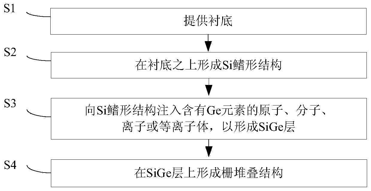
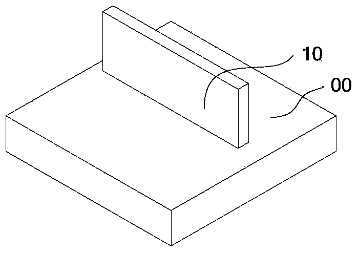
The invention provides a fin-shaped field effect transistor with a SiGe channel and a forming method of the fin-shaped field effect transistor. The forming method includes the following steps of providing a substrate, forming a Si fin-shaped structure on the upper portion of the substrate, injecting atoms, molecules, ions or plasmas containing Ge elements into the Si fin-shaped structure so that the SiGe layer can be formed, and forming a gate stacking structure on the upper portion of the SiGe layer. According to the forming method, the FinFET with the SiGe channel can be formed, the SiGe channel is thin and good in quality, and accordingly the forming method has the advantages of being simple, easy to carry out and low in cost.

Description

technical field [0001] The invention relates to the field of semiconductor manufacturing, in particular to a fin field effect transistor with a SiGe channel and a forming method thereof. Background technique [0002] Metal-oxide-semiconductor field-effect transistors (MOSFETs) have served the integrated circuit industry for over forty years. People have invented a variety of ingenious techniques to make the feature size shrink continuously, but it has not changed its basic structure. However, the integrated circuit design window, including performance, dynamic power consumption, static power consumption, and device tolerances, has shrunk to the point where a new transistor structure has to be invented. As the gate length continues to shrink, the transfer characteristics (Ids-Vgs) of MOSFETs degrade, mainly in two aspects. One is that the sub-threshold slope becomes larger and the threshold voltage decreases, that is, the MOS device cannot be turned off well by reducing the...

Claims


Application Information

Patent Timeline
IPC IPC(8): H01L21/336H01L29/78H01L29/10
CPCH01L29/66795H01L29/1037H01L29/66803
Inventor 王敬肖磊梁仁荣许军
Owner TSINGHUA UNIV
Why Eureka
Try Eureka