
Suspended filtering system

A technology of suspension filtration and filter head, which is applied in the direction of filtration separation, gravity filter, loose filter material filter, etc. It can solve the problems of large water head and loss, and achieve the effect of small water head loss, saving facility investment and operating costs

Active Publication Date: 2014-08-13
YELLOW RIVER ENG CONSULTING
View PDF9 Cites 10 Cited by
  • Summary
  • Abstract
  • Description
  • Claims
  • Application Information

AI Technical Summary

Problems solved by technology

[0006] The purpose of the present invention is to provide a suspension filtration system to solve the problem of large head loss caused by the forward filtration method of the existing filtration system

Method used


Image

  • Suspended filtering system
  • Suspended filtering system
  • Suspended filtering system

Examples


Embodiment Construction

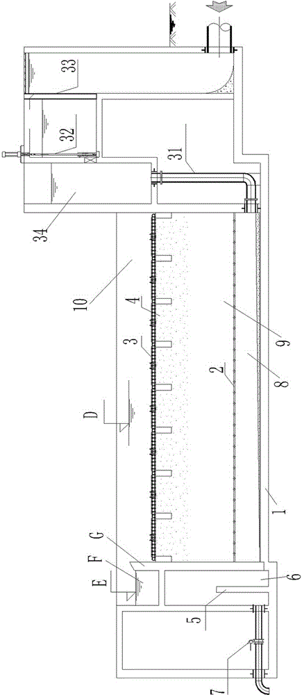
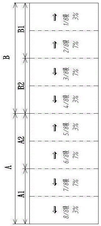
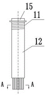
[0023] Suspension filter system of the present invention sees Figure 1-Figure 7 As shown, it includes a filter body 1 and a backwash system. The filter body is provided with an upper filter plate 3 and a water distribution channel top plate 2 at intervals up and down. The upper filter plate and the water distribution channel roof separate the space in the filter body from the upper The bottom interval is divided into three areas, which are in turn: the area above the upper filter plate 3 is the clear water storage area 10, the area below the top plate 2 of the water distribution channel is the raw water distribution channel 8, and the area between the upper filter plate and the top plate of the water distribution channel The area is a filtering area 9, wherein there is a suspended filter material 4 of predetermined thickness in the filtering area, and the density of the filter material is lower than that of water. An overflow wall G is provided between the clean water storage...


PUM

PropertyMeasurementUnit
diameteraaaaaaaaaa
thicknessaaaaaaaaaa
porosityaaaaaaaaaa

Abstract

The invention relates to a suspended filtering system. The suspended filtering system comprises a filtering pool body, wherein the filtering pool body is divided into three areas by an upper filtering plate and a top plate of a water distribution channel from top to bottom; the area above the upper filtering plate is a clean water storage area; the area under the top plate of the water distribution channel is provided with a raw water distribution channel communicated with raw water; the area between the upper filtering plate and the top plate of the water distribution channel is a filtering area; a suspended particle filtering material with preset thickness is contained in the filtering area; filtering head installing holes are distributed in the upper filtering plate and are internally provided with filtering heads; water distribution holes are distributed in the top plate of the water distribution channel. Compared with a traditional forward-flow filtering process, a backward-flow filtering process of the filtering system has the advantages that the water head loss is as less as about 0.6m and is only 1 / 4 of that of conventional filtering; in addition, during back washing, a water head after upper filtering can be utilized, the back washing is realized by means of the gravity action of a water body, and energy consumption is not needed in the back-washing process, so that huge facility investments and operating costs are saved.

Description

technical field [0001] The invention relates to a filter system for water treatment. Background technique [0002] In the current conventional filtration process, the water flow direction of the water to be filtered is generally from the upper part of the filter material to the lower part of the filter material, that is, forward filtration. In this type of filtration process, the density of the filter material used is higher than that of water. At present, the widely used fast filter, V-shaped filter, siphon filter, etc. all adopt this method, and the filter tank disclosed by Chinese patent document CN203458855U also adopts this method. The middle and lower part of the filter pool body is equipped with a filter plate with a filter head, and there are filter materials such as pebbles and quartz sand on the filter plate. It is set at the lower part of the pool wall, and the sewage outlet is opened at the middle and upper part of the pool wall. This kind of filtration method h...

Claims


Application Information

Patent Timeline
Patent Type & Authority Applications(China)
IPC IPC(8): B01D24/26B01D24/46
Inventor 蔡明郭鹏程闫大鹏卢慧陈凯冯赟昀侯晓明苏妍妹刘猛
Owner YELLOW RIVER ENG CONSULTING
Learn More