Adsorption dehumidification process method and device

A process method and dehumidifier technology, applied in the field of dehumidification, can solve the problems of low energy consumption and large energy consumption, and achieve the effect of lowering the temperature and improving the dehumidification effect

Inactive Publication Date: 2018-01-23
GUANGDONG UNIV OF TECH
View PDF5 Cites 0 Cited by
  • Summary
  • Abstract
  • Description
  • Claims
  • Application Information

AI Technical Summary

Problems solved by technology

[0010] The present invention provides an adsorption and dehumidification solution with low energy consumption for removing moisture from gas in order to overcome the disadvantages of large energy consumption in the prior art.

Method used


Image

  • Adsorption dehumidification process method and device
  • Adsorption dehumidification process method and device
  • Adsorption dehumidification process method and device

Examples


Embodiment 1

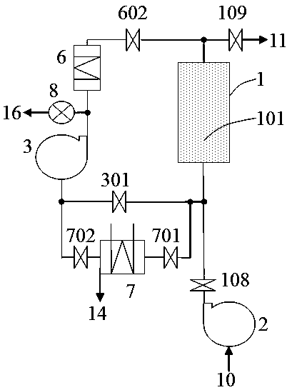
[0107] Such as figure 1 As shown, it is a schematic diagram of an intermittent dehumidification device equipped with a condenser in a regeneration circuit in the present invention. The dehumidification device includes an adsorption dehumidifier 1 (with a hygroscopic agent bed 101 composed of hygroscopic agent particles inside), an inlet 10 for gas to be dehumidified , Dehumidified gas outlet 11, dehumidification fan 2, circulation fan 3, regeneration heater 6, condenser 7. The gas inlet 10 to be dehumidified, the dehumidifying fan 2, the adsorption dehumidifier 1, and the dehumidified gas outlet 11 are connected through pipelines to form a dehumidified gas path. The adsorption dehumidifier 1, the circulating fan 3, and the regeneration heater 6 are connected through pipelines to form a regeneration circuit; both ends of the condenser 7 are connected to the regeneration circuit through pipelines to form a condensation branch, and the valves 301, 701, and 702 can be used to adju...

Embodiment 2

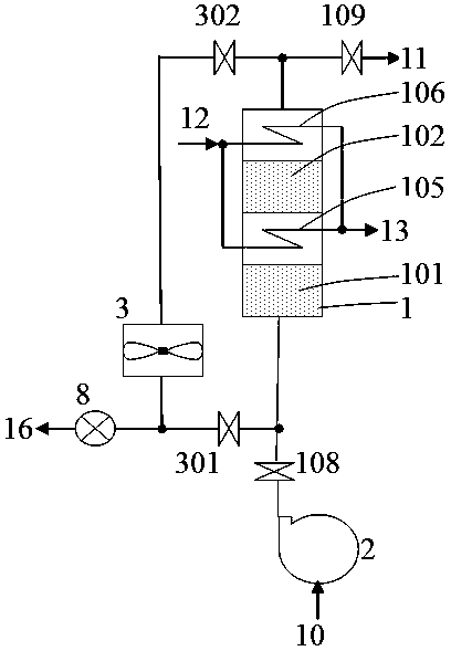
[0121] Such as figure 2 Shown is another intermittent adsorption dehumidification device of the present invention.

[0122] The adsorption dehumidifier 1 has hygroscopic agent beds 101, 102 composed of hygroscopic agent particles and heat exchange tubes 105, 106 spaced apart from the hygroscopic agent beds 101, 102. The heat exchange surfaces of , 106 are in contact with each other to avoid local overheating of the moisture absorbent beds 101, 102; the circulation fan 3 is a two-way axial flow fan; An operating cycle of the device includes dehumidification, regeneration steps:

[0123] (A) Dehumidification: Cooling medium is introduced into the heat exchange tubes 105, 106, valves 108, 109 are opened, other valves are closed, and the dehumidification fan 2 is operated, so that the gas to be dehumidified entering through the inlet 10 flows through the adsorption dehumidifier 1, and the gas The moisture in the gas is adsorbed and removed by the hygroscopic agent beds 101 and ...

Embodiment 3

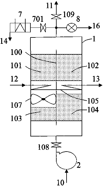
[0134] Such as image 3 Shown is another intermittent adsorption dehumidification device of the present invention.

[0135] The adsorption dehumidifier 1 has moisture absorbent beds 101, 102, 103, 104 composed of moisture absorbent particles, heat exchange tubes 105, and circulation fan 107; the partition 100 divides the interior of the adsorption dehumidifier 1 into two chambers. Running the circulation fan 107 can circulate the gas in the adsorption dehumidifier 1 . An operation cycle of the dehumidification device also includes dehumidification and regeneration steps. When the water needs to be discharged, the valve 701 can be opened. Since the gas pressure in the adsorption dehumidifier 1 is higher than the pressure in the condenser 7, the gas in the adsorption dehumidifier 1 enters the condenser 7, and the water vapor contained in the gas is condensed, and the condensed water is discharged from the port 14 out. The advantage of the dehumidification device with built-in...


PUM


Abstract

An adsorption dehumidification process method and apparatus. First, moisture-containing gas is injected into an adsorption dehumidifier (1) for dehumidification, and then, dehydration regeneration is performed on a moisture absorbent inside the adsorption dehumidifier (1) that has absorbed water. The dehydration regeneration comprises the following steps: step 1: cyclic heating up; step 2: cyclic dehydration regeneration; step 3: water discharging; and step 4: cooling. Step 3 is performed intermittently or continuously, and when the circulation gas contains 60 grams or more of water per kilogram of dry gas, the operation of step 3 starts while step 1 or step 2 is performed. The adsorption dehumidification apparatus comprises a dehumidification gas path having a to-be-dehumidified gas inlet (10), an adsorption dehumidifier (1), a dehumidified gas outlet (11) and a plurality of valves connected thereto, and further comprises a regeneration loop, a regeneration heater (6), a circulation fan (3) and a drainage device. The circulation fan (3) and the regeneration heater (6) are disposed on the regeneration loop, the regeneration loop connects the input end and the output end of the adsorption dehumidifier (1), the circulation fan (3) drives gas to cyclically flow on the regeneration loop, and the drainage device is communicated with the regeneration loop.

Description

technical field [0001] The invention relates to a dehumidification technology suitable for thermal energy, chemical industry, metallurgy, electronics, machinery, light industry and other industries, and more specifically relates to a process method and device for adsorption dehumidification. Background technique [0002] Dehumidification technology is often used to process wet gas to obtain dry gas. In addition to the common air dehumidification of human living environment and air dehumidification of various facilities such as factory workshops and warehouses, many industrial sectors often need to dehumidify chemical raw materials, energy gases such as natural gas and coal gas, and various industrial gases for various purposes. Perform dehumidification. For example, in chemical production, it is necessary to dehumidify the feed gas to below the dew point of -60°C to prevent moisture from reducing the activity of the catalyst. In the energy industry, dehumidification of comp...

Claims


Application Information

Patent Timeline
Patent Type & Authority Patents(China)
IPC IPC(8): B01D53/26B01D53/02
CPCB01D53/02B01D53/26
Inventor 黄海涛
Owner GUANGDONG UNIV OF TECH
Why Eureka
Try Eureka