Jaw crusher

A jaw crusher and frame technology, applied in the field of mechanical equipment, can solve the problems of poor crushing effect and low efficiency, and achieve the effects of increased flexibility, low noise, and convenient component replacement.

Inactive Publication Date: 2014-08-13
SUZHOU TIANMAI THERMAL TECH
View PDF10 Cites 5 Cited by
  • Summary
  • Abstract
  • Description
  • Claims
  • Application Information

AI Technical Summary

Problems solved by technology

[0003] In order to solve the problems of low efficiency and poor crushing effect of existing

Method used


Image

  • Jaw crusher

Examples


Embodiment Construction

[0020] The preferred embodiments of the present invention will be described in detail below in conjunction with the accompanying drawings, so that the advantages and features of the present invention can be more easily understood by those skilled in the art, so as to define the protection scope of the present invention more clearly.

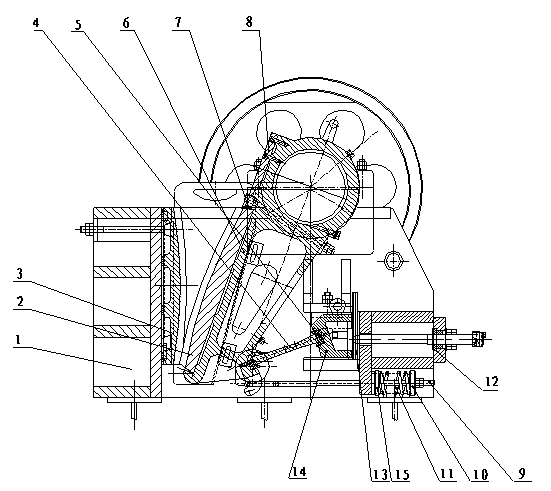
[0021] as attached figure 1 As shown in the structural diagram of the present invention, a jaw crusher includes a frame 1, a movable jaw plate 2 movably mounted on the frame 1, a fixed jaw plate 3 fixedly mounted on the frame 1, and one end movable The toggle plate 4 installed on one end of the movable jaw plate 2, the movable jaw plate 6 installed on one end of the movable jaw plate 2, the outer spring seat 10 installed on the frame 1, the outer spring seat installed on the outer spring seat The pull rod 9 of 10, the spring 11 sleeved on the pull rod 9, the inner spring seat 15 installed on the frame 1 and located at one end of the pull rod...


PUM


Abstract

The invention provides a jaw crusher. The jaw crusher comprises a rack, a movable jaw, a fixed jaw, a toggle plate, a moving jaw, an outer spring seat, a pull rod, a spring and an inner spring seat, wherein the movable jaw is movably installed on the rack; the fixed jaw is fixedly installed on the rack; one end of the toggle plate is movably installed at one end of the movable jaw; the moving jaw is installed at one end of the movable jaw; the outer spring seat is installed on the rack; the pull rod is installed on the outer spring seat; the pull rod is sleeved with the spring; the inner spring seat is installed on the rack and arranged at one end of the pull rod. The jaw crusher has the advantages that the jaw crusher has deep crushing cavity and is free from dead zones, thus improving the feeding capacity and the yield; the jaw crusher has high ratio of crushing and uniform product granularity; a gasket type discharge hole adjusting device is reliable and convenient and has large range of adjustment, thus improving the flexibility of equipment; a lubricating system is safe and reliable and parts are convenient to change and have small maintenance workloads; the jaw crusher has a simple structure, operates reliably and is low in operating cost; the discharge hole adjusting range is large, so that the requirements of different users can be met; the jaw crusher has low noise and less dust.

Description

technical field [0001] The invention relates to the field of mechanical equipment, in particular to a breaking hammer machine for crushing materials. Background technique [0002] In large production lines, mechanical equipment is often used to move raw materials from one location to another for subsequent processing and production. Due to the large amount of raw materials used in the production line, and due to the characteristics of the raw materials themselves, the raw materials need to be processed in the form of small pieces or granules when they are used, and the raw materials need to be in the form of large blocks or plates during the molding process. To facilitate storage, transportation and use, etc. Therefore, when this type of raw material is used, it needs to be crushed first, and then moved to the next production process. The existing crushing methods are usually manual crushing or continuous beating with a mechanical hammer to crush the raw materials, or use ...

Claims


Application Information

Patent Timeline
IPC IPC(8): B02C1/04
Inventor 丁幸强
Owner SUZHOU TIANMAI THERMAL TECH
Why Eureka
Try Eureka