

Process for machining corrugated pipe fitting by means of electromagnetic pre-deformation forming technique
A technology of corrugated pipe fittings, which is applied in the field of processing corrugated aluminum alloy energy-absorbing pipe fittings, can solve the problems of insufficient energy absorption efficiency of thin-walled round pipes, and achieve the effects of improving energy absorption efficiency, easy operation, and fast forming speed
- Summary
- Abstract
- Description
- Claims
- Application Information
AI Technical Summary
Problems solved by technology
Method used
Image

Examples
Embodiment 1
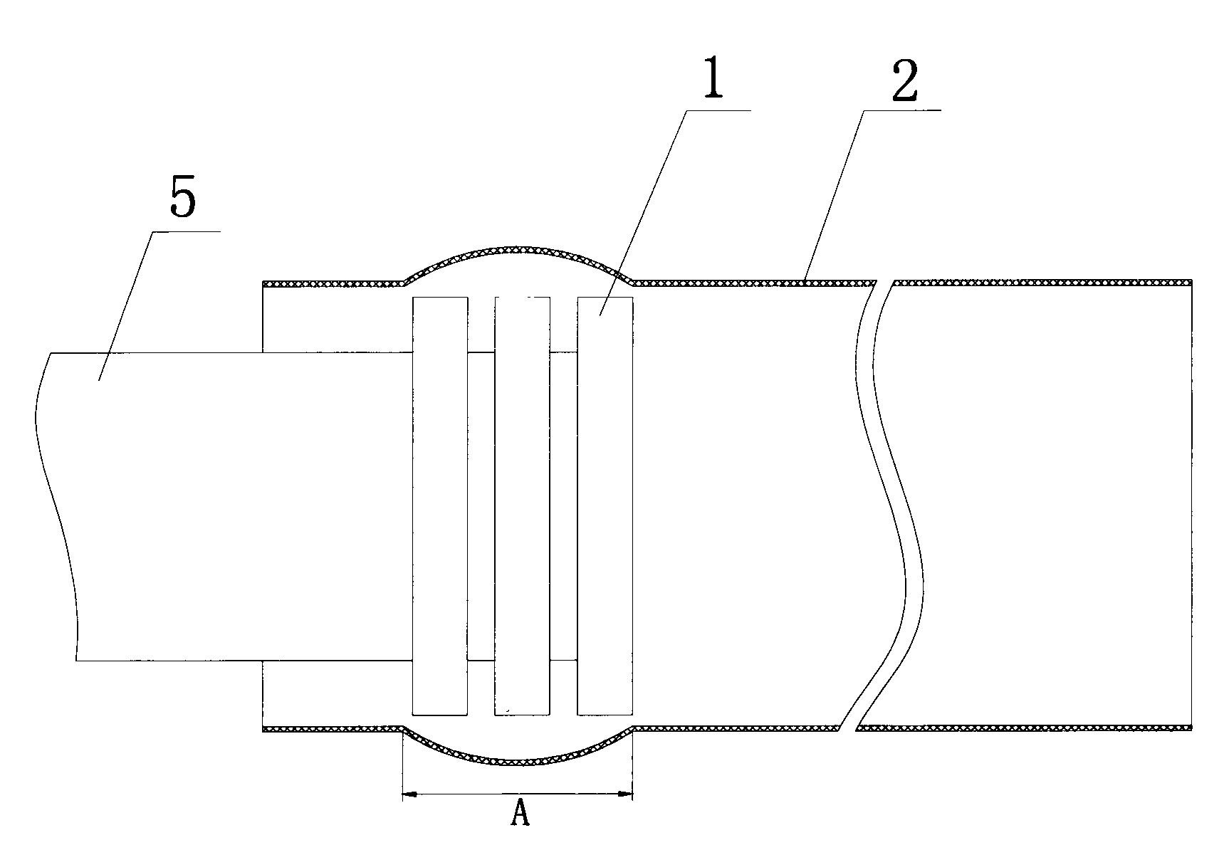
[0023] Embodiment 1, the discharge forming of the bellows without spacing is as follows image 3 , Figure 4 shown.
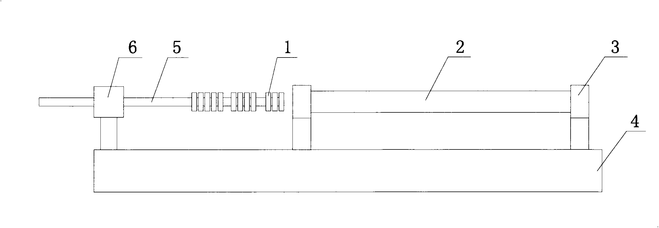
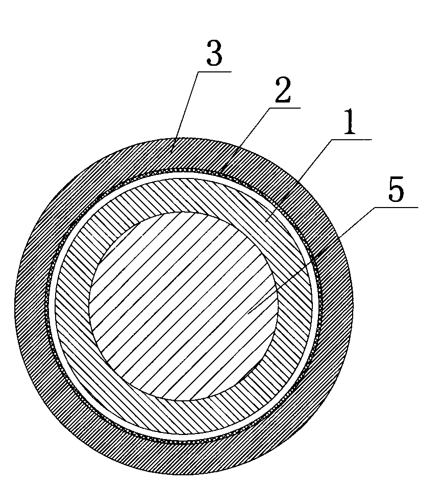
[0024] Step 1: install the pipe fittings; place the pipe fittings 2 in the pipe fitting restraining device 3 for fixing, the pipe fitting 2 is a thin-walled aluminum alloy pipe fitting, the wall thickness = 1.2mm, ensure that the pipe fitting restraining device 3 and the pipe fitting 2 axis coincide, pass The coil guide rod 5 places the solenoid coil 1 at the position where the pipe member 2 is to be bulged.
[0025] Step 2: The number of turns of the solenoid coil 1 is 3, the capacitance of the charging capacitor bank C is 768-1152μF, the resistance R is 0.01Ω-0.03Ω, and the Z parameter of the rectifier is reverse bias voltage 50kV / average current not less than 3.5A , the transformer P parameter is 220V-8kV, close the discharge control switch K, the capacitor bank C discharges through the solenoid coil 1, the discharge voltage is 1000-3500V, and the forming ...
Embodiment 2
[0027] Example 2, discharge forming of corrugated pipes with different pitches.
[0028] Step 1, with embodiment 1
[0029] Step 2: By adjusting the advance amount of the coil guide rod 5 to the solenoid coil 1, the corrugated pipe parts with different pitches are processed, and a is the pitch between the corrugations. Turn off the discharge control switch K, the capacitor bank C discharges through the solenoid coil 1, the parameters are the same as those in embodiment 1, and a ripple is formed under the action of electromagnetic force. To ensure that the pipe restraint device 3 and the pipe 2 do not move, the solenoid coil 1 advances a larger distance inside the pipe 2, and the distance between the corrugations increases, thereby forming corrugations with different distances. By continuously adjusting the advance of the solenoid coil 1 , corrugations with different pitches are formed on the pipe 2 .
[0030] Step 3: Same as Example 1.
Embodiment 3
[0031] Embodiment 3, pipe fittings with different corrugated widths are discharged into, such as Figure 5 , Figure 6 shown.
[0032] Step 1, with embodiment 1
[0033] Step 2, it is necessary to increase the corrugation width of the pipe fittings by increasing the number of turns of the solenoid coil 1, A is the width of the corrugation, Figure 5 The number of turns of the middle coil is 4, Figure 6 The number of turns in the middle circle is 5. Turn off the discharge control switch K, the capacitor bank C discharges through the solenoid coil 1, the parameters are the same as in the embodiment 1, and the pipe part 2 can be formed into a corrugation with a wide width under the action of electromagnetic force.
[0034] Step 3: Same as Example 1.
[0035] The present invention forms corrugations on thin-walled circular pipes. The adjustment and matching of specific dimensional parameters such as the number of corrugations, width, height, and spacing have a great influenc...
PUM
| Property | Measurement | Unit |
|---|---|---|
| Number of turns | aaaaa | aaaaa |
| Capacitance | aaaaa | aaaaa |
Abstract
Description
Claims
Application Information