
On-site Machining Method of Generator Rotor Yoke Keyway

A technology of generator rotor and process method, which is applied in the direction of metal processing equipment, manufacturing tools, broaching machines, etc., which can solve problems affecting the insertion of gaskets and convex keys, uneven air gaps, unit vibration, etc., so as to facilitate repair and replacement , wide range of processing height and controllable feed speed

Active Publication Date: 2016-05-25
HARBIN ELECTRIC MASCH CO LTD
View PDF4 Cites 0 Cited by
  • Summary
  • Abstract
  • Description
  • Claims
  • Application Information

AI Technical Summary

Problems solved by technology

Due to comprehensive reasons such as tolerance accumulation during the yoke lamination and preloading process, it is easy to cause radial misalignment of the keyway at the inner circle of the yoke, which will cause waves on the surface of the keyway and affect the flatness of the keyway
Because the follow-up yoke needs to be heated and gasketed, the flatness of the keyway is highly required. If the surface of the keyway of the yoke is not smooth enough, it will affect the normal insertion of the gasket and the convex key, and then affect the thermal fit of the yoke. Quantity value
In severe cases, it will affect the normal operation of the generator, change the roundness of the rotor, cause uneven air gaps, and cause vibration of the unit.
There are no suitable tools and techniques for processing the blanks of laser cutting, so it is necessary to process the keyway of the yoke during the installation process, so that the flatness of the keyway can meet the installation requirements of thermal gaskets, and provide for the subsequent process of the rotor. strong guarantee

Method used


Image

  • On-site Machining Method of Generator Rotor Yoke Keyway
  • On-site Machining Method of Generator Rotor Yoke Keyway
  • On-site Machining Method of Generator Rotor Yoke Keyway

Examples


Embodiment Construction

[0024] A process method for on-site machining of generator rotor yoke keyways, the method comprising the following steps:

[0025] Step 1: Machining the yoke keyway

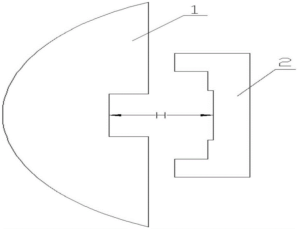
[0026] 1) if figure 1 As shown, after measuring the roundness, concentricity and verticality of the upper and lower sections of the yoke 1, measure the thickness of the keyway of the yoke 1;

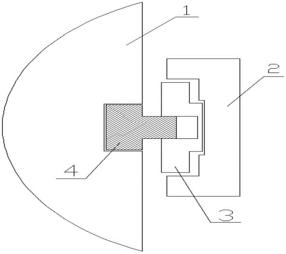
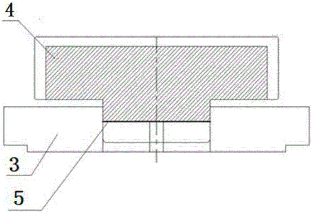
[0027] 2) Install the keyway push-pull knife and auxiliary tools. The keyway push-pull knife is composed of a knife body 4 and a supporting plate 3. The knife body 4 adopts a three-sided edge structure and is made of 9SiCr. The cutter body 4 and the supporting plate 3 are fixed with countersunk screws, and the milling direction is kept perpendicular to the punching surface of the yoke 1 during use, so that the cutting force can effectively act on the yoke 1, such as image 3 shown. A spacer 5 can be added between the cutter body 4 and the supporting plate 3 to effectively adjust the radial size of the tool. For laser cut...


PUM


Abstract

The invention relates to a technology method for processing a magnetic yoke key groove of a generator rotor in a construction site. The technology method is characterized in that a dedicated tool is utilized for processing, a push-pull cutter is placed in a main vertical rib 2 of a rotor support, guiding is carried out by a magnetic yoke key groove cutter body 4 during processing, the bottom surface of a supporting plate 3 is not used for locating, and interference and abrasion are avoided; the tool does reciprocating motion along the axial direction of the magnetic yoke key groove during the processing, the magnetic yoke key groove is processed in the construction site, the wave degree in the magnetic yoke key groove is removed, and the magnetic yoke key groove is enabled to be smooth for conveniently adding a gasket. The technology method adopting the tool can be applied to a magnetic yoke punching sheet in higher edge hardness by laser cutting and blanking and can also be applied to a magnetic yoke punching sheet by blanking of a punching machine, and the application range is wide; the normal injecting of the gasket and a magnetic yoke convex key after a magnetic yoke 1 is heated can be ensured by utilizing the cutter for processing the key groove, a numerical value of thermal sleeving amount of the magnetic yoke can be effectively ensured, and necessary protection is provided for safe and stable running of the generator rotor and a unit.

Description

Technical field: [0001] The invention relates to a process method for on-site machining of generator rotor yoke key grooves. Background technique: [0002] The rotor yoke of the hydro-generator is usually laminated at the construction site, and regular shaping work is required during the lamination process. Since the rotor yoke usually exceeds 2m, multiple preloads are required to fully compress the yoke to make the yoke compress The tightening force meets the design requirements. Due to comprehensive reasons such as tolerance accumulation during the yoke lamination and preloading process, it is easy to cause radial misalignment of the keyway at the inner circle of the yoke, which will cause waves on the surface of the keyway and affect the flatness of the keyway. Because the follow-up yoke needs to be heated and gasketed, the flatness of the keyway is highly required. If the surface of the keyway of the yoke is not smooth enough, it will affect the normal insertion of the ...

Claims


Application Information

Patent Timeline
Patent Type & Authority Patents(China)
IPC IPC(8): B23P15/00B23D37/00
CPCB23D37/00B23P15/00
Inventor 周峰刘艳华宋佳音
Owner HARBIN ELECTRIC MASCH CO LTD
Learn More